Appendix – ethernet/ip gateway option, Introduction, Wiring – TCI HGA Manual User Manual
Page 102
102
Appendix – Ethernet/IP Gateway Option
Introduction
The EtherNet/IP network Communications Gateway translates command/status data to/from the HMI
Display’s integrated network interface from the ModbusRTU protocol to EtherNet/IP. The EtherNet/IP
Communications Gateway is implemented using a third party, industry leading EtherNet/IP solution from
HMS Anybus Communicator Product Line (Anybus Communicator AB7007).
Table 9.1 – EtherNet/IP Communications Gateway Key Features
Feature
Description
Profile Support
EtherNet/IP level 2 I/O Server CIP (ControlNet & DeviceNet),
EtherNet/IP Adapter Class Device
Connection
10/100 MBit twisted pair RJ45 Connection
Galvanic Isolation
Transformer isolated Ethernet interface
TCP/IP Settings
Web Browser Based Configuration
Baud Rate
10/100 MBit auto detect
Protocol
Conformance
Fully compliant EtherNet/IP gateway (ODVA File Number E-090-
10070). See HMS websit for Conformance Test
Results.
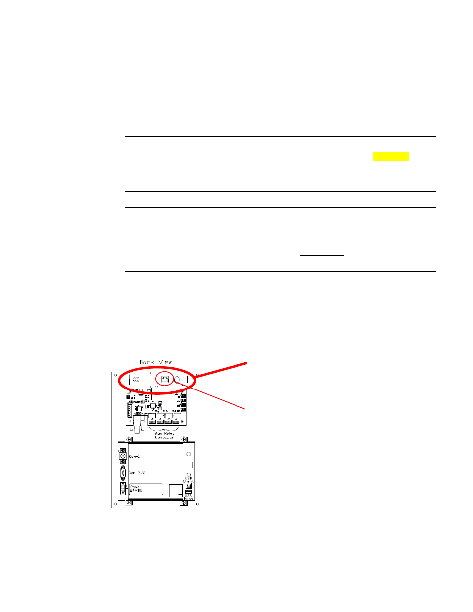
Wiring
Connection of the HarmonicGuard Active filter Interface Module to the end user’s upstream EtherNet/IP
network occurs at the RJ45 connection (see Table 9.1) on the Communications Gateway. The
Communication Gateway is mounted on the back panel of the Interface Module (see Figure 9.2).
Figure 9.2 – EtherNet/IP Communications Gateway Location
EtherNet/IP
Communications
Gateway
RJ45 Connection
to End User
Network