Section 6, Overview, Hmi introduction – TCI HGA Manual User Manual
Page 68
68
■ Section 6
HMI Introduction
The Interface Module provides the user with a convenient way to monitor the operation of TCI’s
HarmonicGuard Active filter and allows for the ability to adjust run-time set-points under password control.
This section describes how to install, operate, and maintain the Interface Module.
Overview
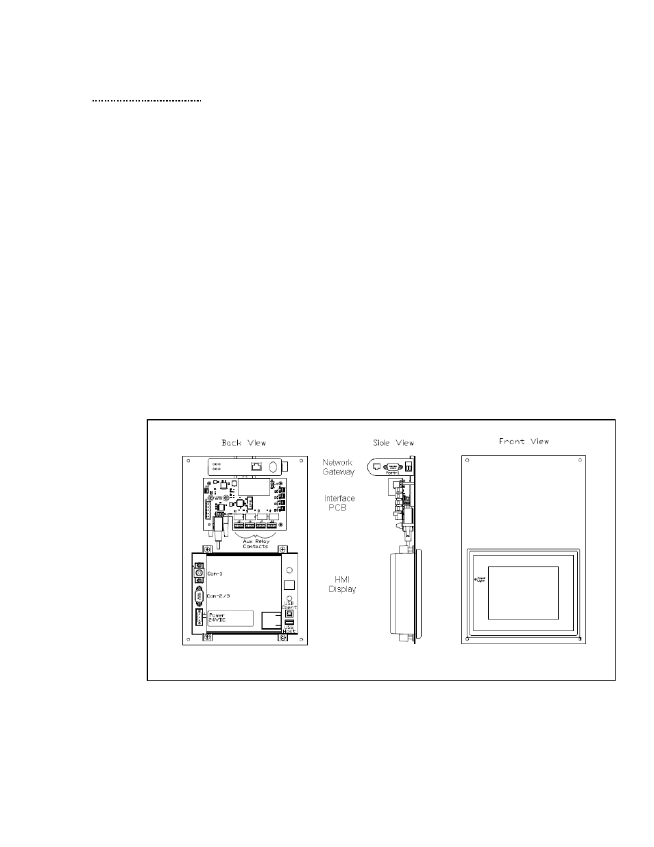
The Interface Module has three major components; the Interface PCB, the HMI Display and an option
network Communications Gateway (see Figure 6.1).
The interface PCB contains a Chassis Communications Port that connects to the power converter of the
HarmonicGuard Active filter. The interface PCB translates status and commands data between the power
converter controls and the HMI Display. The interface PCB also contains the 24V Relay I/O for basic status
monitoring and run/stop control of the HarmonicGuard Active filter.
The HMI Display is a 6” color Touchscreen display containing a series of status screens that provide the user
with a convenient way to monitor the operation of the HarmonicGuard Active filter. The HMI display also
contains an integrated ModbusRTU network connection for remote monitoring of the HarmonicGuard Active
filter.
The optional network Communications Gateway can be connected to the integrated ModbusRTU network
connection in the HMI Display to translate the ModbusRTU protocol to an alternate Fieldbus or Industrial
Ethernet protocol such as Ethernet/IP.
Figure 6.1 – Interface Module Components