Interface pcb connections – TCI HGA Manual User Manual
Page 72
72
Interface PCB Connections
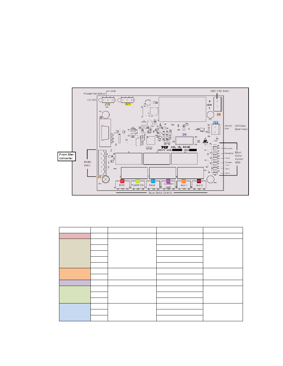
Most customer connections to the Interface module will be made on the Interface PCB. Refer to connection
diagrams in Figure 6.3. The details of the power and communications terminals are shown in Table 6.1, form
C relays are available on the Interface PCB. These connections are shown in Table 6.2. Four outputs are
available on the Interface PCB.
The relay start command input connection on J22 of the interface PCB allows a contact closure to send a run
command to the HarmonicGuard Active filter. The relay start command input will only be acknowledge if the
Relay Run/Stop Enable is set to Enabled on the HMI Display setup screen. See Figure 7.14 for details.
Pressing stop locally via the HMI Display will set the enable for the relay start command to DISABLED.
Figure 6.3 – Interface PCB connections
Table 6.1 – Power & Communications Terminals
Terminal
Pin
Description
Label
Rating
J1
1
HMI Display
For factory use
N/A
J2
1
RS485
Not Connected
N/A
2
B
3
Ground
4
A
5
Not connected
J3
1
Input Power
Neutral
120 VAC
2
Line
J4
1
Micro Programming
For factory use
N/A
J19
1
HMI Power Supply
24 VDC
24 VDC
2
Common
3
Not Connected
J22
1
Start Command
24 VDC
Contact Closure
2
Start
Note: The power terminal on the back of the HMI display accepts 28 to 14 AWG stranded wire, with a
tightening torque of 4.4 in-lb (0.5 Nm).