TCI HGA Manual User Manual
Page 77
77
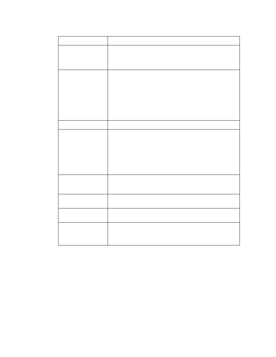
Table 7.2 – Home Screen Elements
Screen Element
Description
Filter Status Display
Indicates if a converter fault is active and preventing the
HarmonicGuard Active filter from running. If a fault occurs the
indicator will flash red and display “Fault”. Specific Fault codes
can be viewed on the “Fault” Screen.
% Filter Current Used
Display
This gauge displays the current filter capacity as a percentage
of total available capacity. In normal operation the display will
read “Nominal”. If the unit output corrective current is above
95% of maximum capacity the indicator light will turn red and
display “At Capacity”. When the converter is at capacity the
Relay K4 (J12 Connector), and J11 Contacts used for a remote
indicator will also be energized. If the monitor continually
displays “At Capacity” a second filter may be required to handle
the load. Please contact TCI for assistance.
Run/Stop Button
Runs and stops the HarmonicGuard Active filter.
System State
Indicator (located
immediately below
stop button)
When the HarmonicGuard Active filter is in a stop mode the
“Status” light will turn red and display “Stopped”. When the
converter is running the status light will be green and will
display “Running”. The status light will also show if the
HarmonicGuard Active filter is in Input line Sync mode, Reset
mode, Precharge mode, Calibrate mode, Power Save mode or
Faulted. When the HarmonicGuard Active filter is faulted it will
shut down automatically
Power Factor Display
Displays current line/load power factor. 1.00 indicates unity
power factor. A negative power factor indicates lagging power
factor.
Line Frequency
Display
Displays the current utility line frequency in Hz.
Supply Voltage
Displays the supply voltage coming into the HarmonicGuard
Active filter.
Line/Load Current
Display
Displays the current line/load phase current in Amps RMS.
NOTE: the displayed current is affected by the CT Ratio
configuration on the “Setup” page.