Connection diagram – TCI HGA Manual User Manual
Page 31
31
Table 4.1b – Power Terminal Wire Size (without breaker) Capacity Range and Tightening Torque
Caution
Use copper wire that is appropriate for the voltage and current rating of the equipment. The wire
selection must conform to the requirements of the National Electrical Code and/or other applicable
electrical codes.
Use wire with an insulation temperature rating of 75°C or higher.
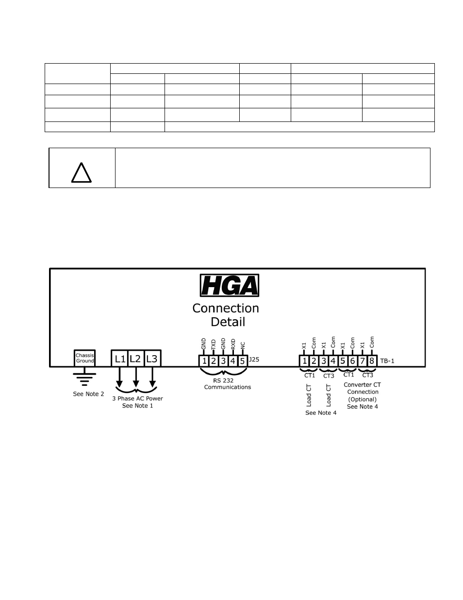
Connection Diagram
Figure 4.3 shows the typical wiring connections between the models of the HGA and the load. Refer
to the drawings furnished with the unit for more specific information.
• The input 3-phase AC voltage source must be connected in a positive ABC phase rotation
from L1-L2-L3 for correct unit operation.
Figure 4.3 – Typical Load Connection Diagram
Notes:
1.) Wiring should be 75°C or higher insulated copper, with the appropriate voltage and current rating.
2.) Chassis ground must be connected to the ground of the premises wiring system, in accordance
with NEC and local codes. Connection must be made using a wire conductor.
3.) Terminal TB-I & J25 wire range is 30-12 AWG, tightening torque is 4.4 IN-LB (0.5 NM).
4.) Operating current transformers with the secondary winding open can result in a high voltage
across the secondary terminals which may be dangerous to personnel or equipment.
Chassis Size
Ground Lug
Power Terminals
Wire Size
Torque In-lbs (Nm)
Breaker IC
Wire Size
Torque In-lbs (Nm)
39 to 100 Amp
14 AWG – 2/0
120 (13.6)
25 to 100 kA
14 – 2/0 AWG
180 (20.3)
150 to 200 Amp
14 AWG – 2/0
120 (13.6)
25 to 100 kA
6 AWG – 350 MCM
274 (31)
150 to 200 Amp
14 AWG – 2/0
120 (13.6)
None
6 AWG – 350 MCM
274 (31)
Control Terminals
Wire Size 28 to 14 AWG Torque 4.4 in-lb (0.5 Nm)
!