TCI HGA Manual User Manual
Page 83
83
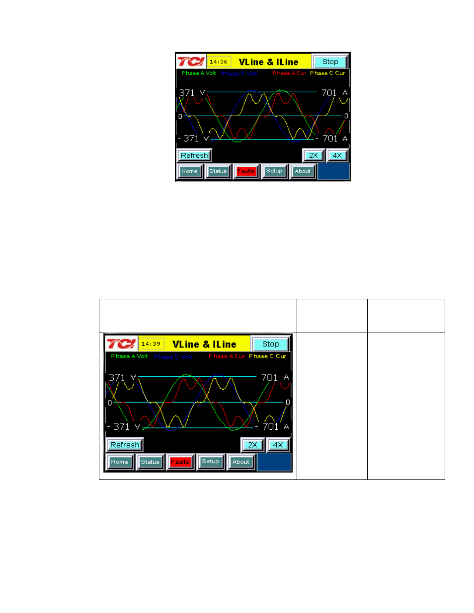
Figure 7.8 – VLine & ILine Waveform Plot of a Properly Connected
HarmonicGuard Active filter (unit in stopped state)
Note: The example VLine & ILine Waveform Plot screens apply to rectifier loads only. For low power factor
loads the VLine & ILine waveform screen will appear different.
Table 7.8 shows what the VLine & ILine Waveform Plot Sub Screen would look like with various
connection errors present in the system.
Table 7.8 – VLine & ILine Waveform Plot Screen Examples when
Typical Connections Errors Present in System
VLine & ILine Waveform Plot Sub Screen with
Rectifier Load
Connection
Error
Description
Connection Error
Resolution
Phase rotation is
Incorrect:
Phase A leads
Phase C instead
of Phase C
leading Phase A.
To correct swap
Phase A and Phase
C HarmonicGuard
Active filter power
connections AND
swap Phase A and
Phase C system CT
current feedback
then recheck plot.