Converter inspection – TCI HGA Manual User Manual
Page 54
54
Converter Inspection
• Verify that power has been removed from converter, and 5 minutes has passed before
inspection.
• Remove plastic cover from over converter section.
• Visually check the circuit boards for debris; contamination; overheated traces; burnt
circuit board; overheated, cracked, or broken components; corrosion; and poor solder
joints.
• Check all wires and terminals connected to the circuit boards.
• Check the four electrolytic capacitors for bulges, ruptures, popped vent plugs,
discoloration, or leakage.
• Check the power semiconductors mounted to heat-sink for cracked cases, ruptures,
debris, arcing, and burning.
• Check for any loose connections if no apparent damage is found to the power
semiconductors.
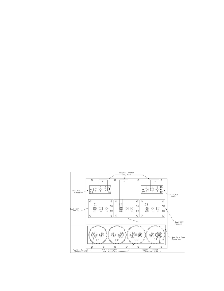
• Measure resistance of power semiconductors using a multimeter set on the diode check
setting, see Figure 5.2.
Look for opens, ∞,
or dead short readings. With the red lead of
your meter connected to the far right negative terminal of the capacitor bank, measure
with the black lead of the meter to each of the three output terminals (bus bars), the
reading should be approximately 0.35Ω. Reverse the meter leads and repeat measuring to
each terminal. This time a low reading will be present which will continue to increase;
this is an indication of a capacitor charging. Next connect the black meter lead to the
“positive capacitor terminal” and again measure to each of the output terminals with the
other lead; the reading should be approximately 0.35
Ω
.
Reverse the meter leads and
repeat measuring to each terminal. Again it will be a low reading which will continue to
increase. If the readings are as described, in all likelihood the power semiconductors are
good. If any readings are opens or dead shorts it will be an indication that something is
bad in the power section. Do not reapply power if you are not sure the IGBT’s are good.
Figure 5.2 – 39, 45, 78, 90, 100, and 200 Amp Power Component Layout