Hmi display connections – TCI HGA Manual User Manual
Page 73
73
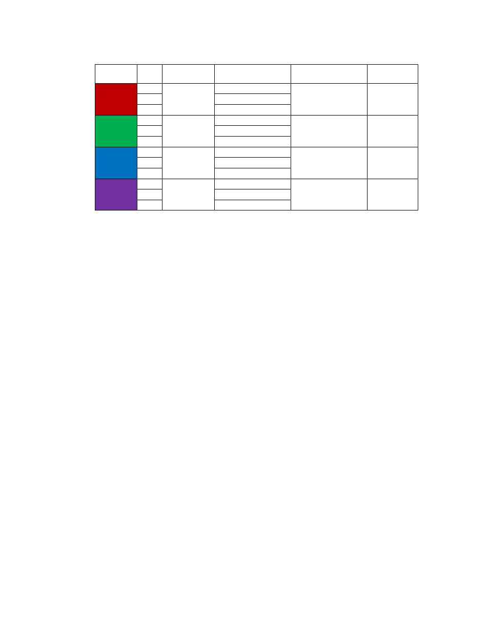
Table 6.2 – Form C Relay Contacts
Terminal
Pin
Description
Label
Tightening
Torque
Wire
Range
J5
1
Run
Normally Closed
4.4 lbs-in (0.5 Nm)
28-14 Awg
2
Common
3
Normally Open
J6
1
Power On
Normally Closed
4.4 lbs-in (0.5 Nm)
28-14 Awg
2
Common
3
Normally Open
J7
1
Fault
Normally Closed
4.4 lbs-in (0.5 Nm)
28-14 Awg
2
Common
3
Normally Open
J12
1
Current
Limit
Normally Closed
4.4 lbs-in (0.5 Nm)
28-14 Awg
2
Common
3
Normally Open
Note: Form-C relay contacts are gold plated with a load rating of 0.6A @ 125VAC general use; 0.2A @
250VAC, 0.6A @ 125VAC, 2A @ 30VDC resistive. The minimum permissible load rating is 10uA, 10mVDC.
HMI Display Connections
Note: The following section describes the default ModbusRTU network connection available on the base
model. If an optional advanced network Communications Gateway is included in the Interface Module see
the appendix for the specific Communications Gateway configuration.
The HMI display implements a ModbusRTU slave device over RS-485. This network connection is available
on the COM2/3 DB9 connector on the back of the HMI Display (see Figure 6.4).
The output registers from the HarmonicGuard Active filter are mapped to Modbus register address 40500.
The input registers to the HarmonicGuard Active filter are mapped to Modbus register address 40564. For
definitions of the input and output data available via the network connection see the Network Interface
section below.
If the optional network Communications Gateway is present the integrated ModbusRTU interface on the HMI
Display will not be available. When configured, the Communications Gateway will occupy the ModbusRTU
COM2/3 DB9 connector on the back of the HMI Display.