MacDon FD75 OM User Manual
Page 77
6.
Fully lower the combine feeder house and float the
header up off the down stops (float indicator should be
on 4 and the adapter should be fully separated from
the header).
NOTE:
You may need to hold the header down switch
for a few seconds to ensure the feeder house is
entirely down.
7.
Read voltage.
8.
Raise header so cutterbar is 6 in.
(150 mm) off
the ground.
9.
Read voltage.
10. If the sensor voltage is not within the low and high
limits refer to
Height Sensor Output Voltage Range
– Combine Requirements, page 58
, or if the range
between the low and high limits is insufficient, you
need to make adjustments. Refer to
for instructions.
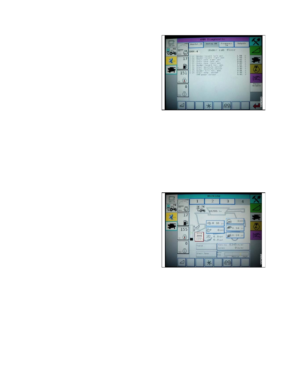
Figure 4.44: Combine Display
Engaging the Auto Header Height System (AGCO 6 Series)
NOTE:
Changes may have been made to the combine controls or display since this document was published.
Refer to the combine operator’s manual for updates.
The following system components are required in order for
the Auto Header Height system to work:
• Main module (PCB board) and header driver module
(PCB board) mounted in card box in Fuse Panel
Module (FP).
• Multi Function Control Handle operator inputs.
• Operator inputs mounted in the control console module
(CC) panel.
NOTE:
In addition to the above components, the electro
hydraulic header lift control valve must also be
considered an integral part of the system.
To select the AHHC mode, scroll through the header control
options using the header control switch until the AHHC icon
is displayed in the first message box.
When activated, the AHHC will adjust the header height in
relation to the ground according to the height setting and
sensitivity setting.
Figure 4.45: Combine Display
169894
63
Revision A