MacDon FD75 OM User Manual
Page 68
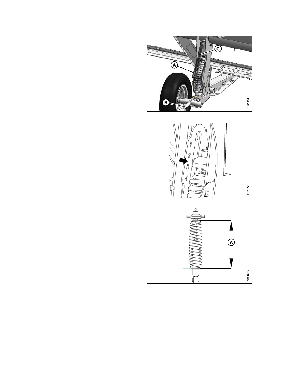
2.
Support wheel weight by lifting slightly with one hand
on handle (B). Pull up on handle (A) to release lock.
3.
Lift wheel with handle (B) and engage support channel
into center slot (C) in upper support.
4.
Push down on handle (A) to lock.
Figure 4.28: Stabilizer Wheel
5.
Lower header to desired cutting height using combine
controls and check load indicator.
As an example
the image shows that the wheels are set to a range
between ‘2’ and ‘3’ on load indicator.
Figure 4.29: Load Indicator
IMPORTANT:
Continuous
operation
with
excessive
spring
compression (i.e., load Indicator reading greater
than ‘4’ or a compressed length less than 11-5/8 in.
[295 mm]) (A) can result in damage to suspension
system.
6.
Adjust header angle to desired working angle with the
machine’s header angle controls. If angle is not critical,
set it to mid-position.
7.
Use the combine’s Auto Header Height Control
(AHHC) to automatically maintain cutting height. Refer
to
4.7.2 Auto Header Height Control, page 56
and your
combine operator’s manual for details.
NOTE:
The height sensor on the CA25 adapter must be
connected to the combine height control system
in the cab.
Figure 4.30: Spring Compression
169894
54
Revision A