MacDon FD75 OM User Manual
Page 120
6.
With AHC SENSING selected, select the icon with the
arrow in the box (A) on the bottom right of the page.
AHC SENSING appears and provides five pages
of information.
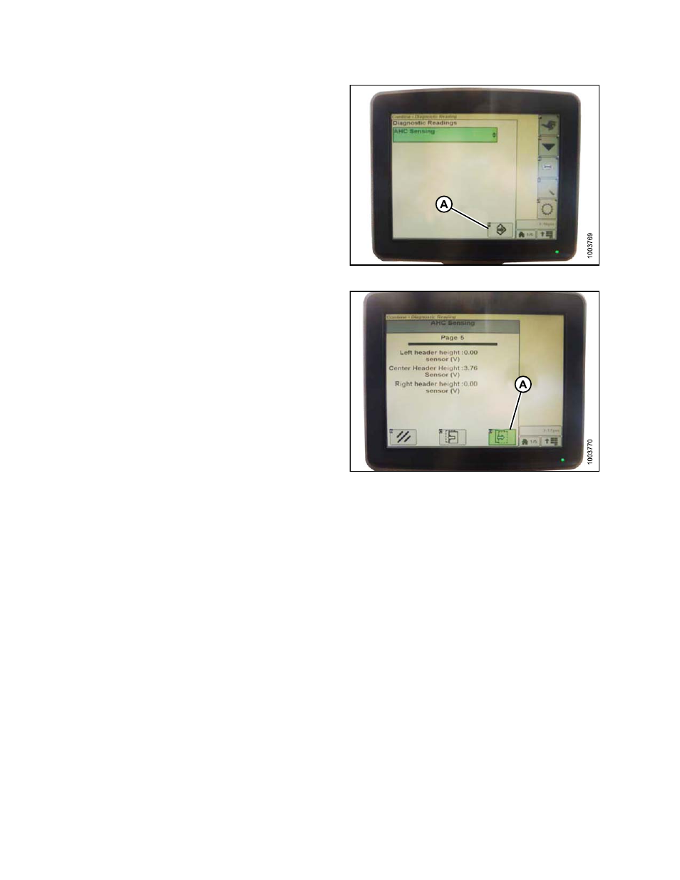
Figure 4.131: Combine Display
7.
Scroll to Page 5 by pressing icon (A) until it reads Page
5 near the top of the page.
On Page 5 you will see sensor readings:
• LEFT HEADER HEIGHT
• CENTER HEADER HEIGHT
• RIGHT HEADER HEIGHT
There is only a reading on the center Header Height
sensor.
On the MacDon header there is only one
sensor, it is located in the float indicator box on top of
the CA25.
Figure 4.132: Combine Display
8.
Ensure header float is unlocked.
9.
Start the combine, lower feeder house to the ground
until the feeder house stops moving.
NOTE:
You may need to hold the header down switch
for a few seconds to ensure the feeder house is
entirely down.
10. Check the sensor reading.
11. If the sensor voltage is not within the low and high
limits shown in
Height Sensor Output Voltage Range
– Combine Requirements, page 58
, or if the range
between the low and high limits is insufficient, you
need to make adjustments. For instructions, refer to
Adjusting Voltage Limits, page 60
.
Calibrating the Auto Header Height System (John Deere S Series)
NOTE:
Changes may have been made to the combine controls or display since this document was published.
Refer to the combine operator’s manual for updates.
169894
106
Revision A