Digital outputs and analog inputs and outputs – Lenze 931E/K Small Drives Control User Manual
Page 107
Digital outputs and analog inputs and outputs
Digital outputs DOUT1, DOUT2
l
107
SW−HB 13.0002−EN 4.1
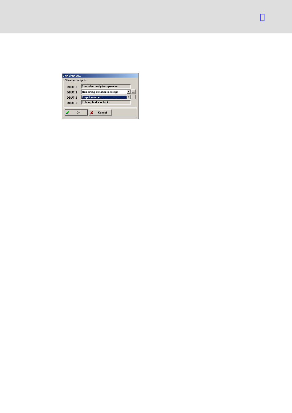
Settings
Select the menu Parameters
W I/Os W Digital outputs to set the parameters of the digital
outputs DOUT1 and DOUT2.
931e_318
DOUT1 and DOUT2 can each be independently assigned with one of the following signals:
ƒ
OFF, i.e. output inactive, LOW level via integrated pull−down resistor
ƒ
ON, i.e. output active, 24 V HIGH level via integrated high−side switch
ƒ
Power stage active, i.e. power stage switched on
ƒ
I
@T message motor / servo
ƒ
Group warning
ƒ
Group error message
ƒ
Following error
ƒ
Remaining path message
ƒ
Target reached
ƒ
Homing completed
ƒ
Comparison speed reached
ƒ
Course program
With some selections, there is a button with three points behind the selection box. If you
click this button, a window opens in which you can enter additional settings.
Setting the messages for the digital outputs
When used together with a control, it may be useful in many applications that the servo
positioning controller generates a message, if the selected operating conditions are not
complied with or not reached. Select the menu item Parameters
W Messages to open the
window for setting the messages. Here, you can select the tolerance margins for the
messages "Comparison speed reached", "Target reached" and "Following error".