Control technology | ethercat communication manual – Lenze EtherCAT control technology User Manual
Page 94
Control technology | EtherCAT communication manual
EtherCAT with CANopen or PROFIBUS
Addressing EtherCAT nodes using CANopen/PROFIBUS nodes
94
L
DMS 3.1 EN 01/2011 TD17
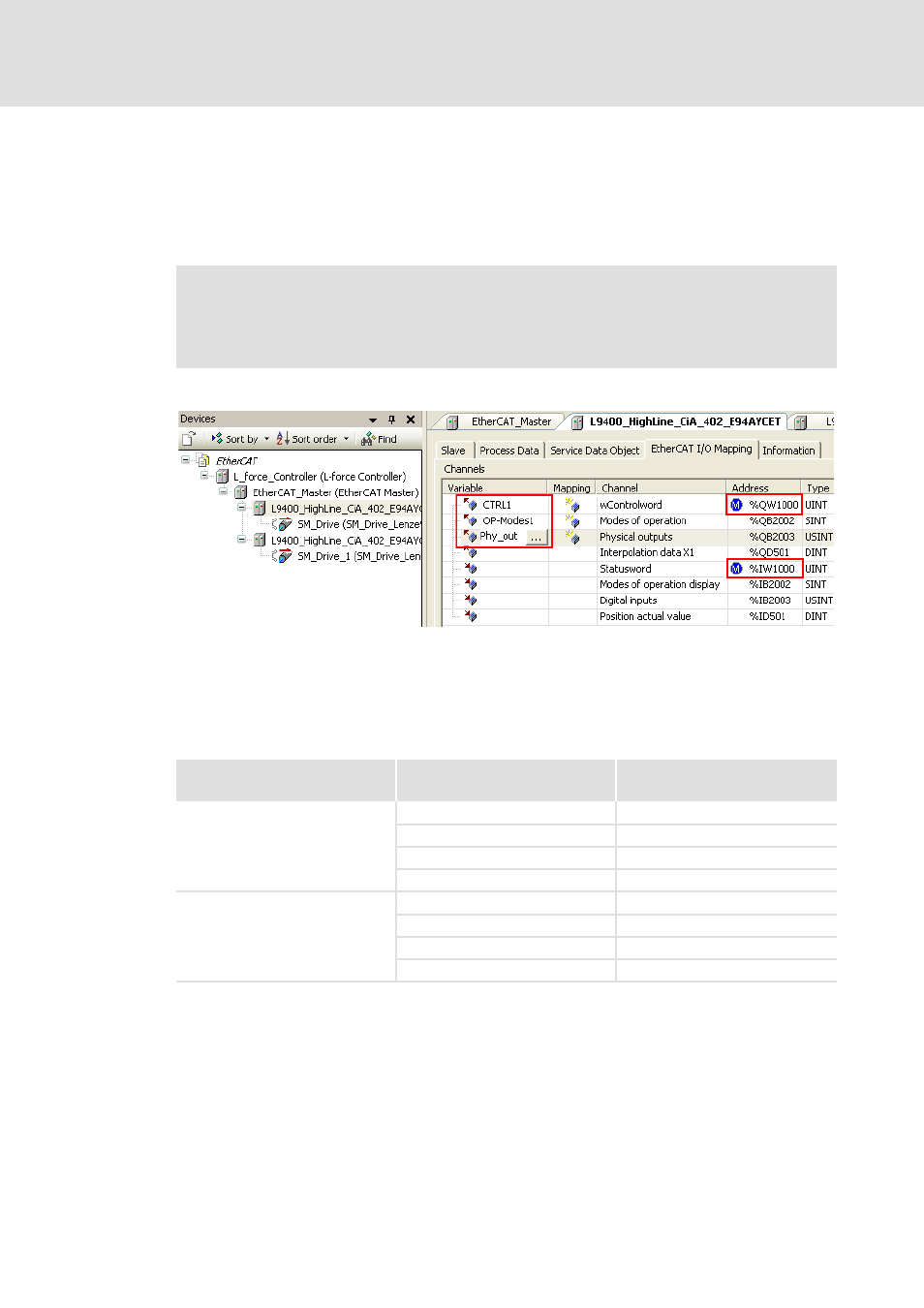
Settings in the »EtherCAT Configurator«
Assign non-ambiguous variable names to the input and output objects according to
IEC 61131 syntax (no blanks and leading digits in the variable name). After the import
of the EtherCAT configuration into the »PLC Designer« control configuration,
corresponding system variables are available for the PLC program.
By double-clicking the corresponding fields, you can make the adjustments:
In the example, variable names have been assigned to the first three output objects.
Moreover, an offset of ’1000’ has been entered for the first output object (%QW...) and the
first input object (%IW...).
The »EtherCAT Configurator« does not work with byte addresses. The objects are
addressed with the byte address in the control configuration:
Note!
Always use the system variables within the PLC program in order to access the
input and output objects or assign values to them.
Objects
Addresses in the
»EtherCAT Configurator«
Byte addresses
Output objects
%QX1000.0
%QB1000
%QB1000
%QB1000
%QW1000
%QB500
%QD1000
%QB250
Input objects
%IX1000.0
%IB1000
%IB1000
%IB1000
%IW1000
%IB500
%ID1000
%IB250