8 a start, 9 monitoring of the supply voltage drop, 10 firing-pulse inhibit – JUMO 709061 TYA 201 - Single-Phase Power Controller Operating Manual User Manual
Page 86: Monitoring of the supply voltage drop, Firing-pulse inhibit, 6 special device functions, 8 α start
6 Special device functions
84
2012-12-01/00561071 [SCR Power Controller TYA201]
6.8
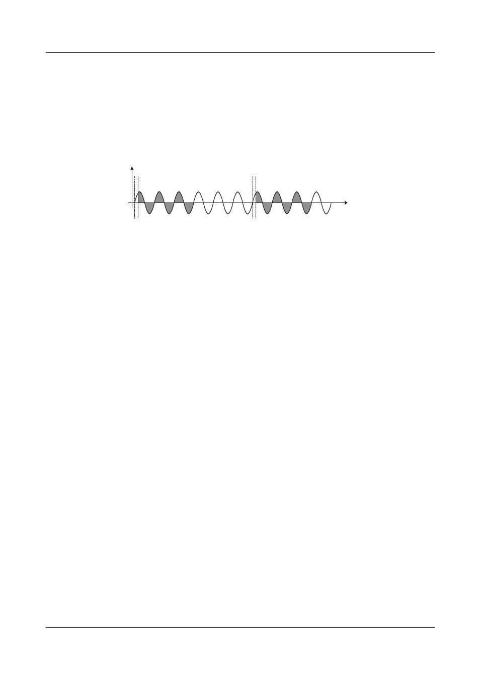
α
start
Factory setting
The phase angle of the first half-wave (
α
start) is not activated.
For transformer loads, the SCR power controllers operate in continuous burst-
firing mode and in logic operation with phase angle control of the first half-
wave.
The factory setting is an angle of 70 °el. (electrical). This value can be adjusted
at the configuration level or operator level within the range of 0 to 90 °el.
6.9 Monitoring of the supply voltage drop
If the effective values of the analyzed half-waves are more than 10 % apart, an
alarm message is displayed and the binary output for the collective alarm
switches depending on the set control direction.
Immediate firing-pulse inhibit prevents the connected transformer loads from
destroying the semi-conductor fuses due to a DC component.
If there are no further supply voltage drops, the firing-pulse inhibit is removed
and the power controller continues operation, e.g. with a soft start.
Factory setting
Monitoring is not activated.
6.10 Firing-pulse inhibit
The inhibit function serves to protect the SCR power controller and the con-
nected devices.
Internal
The SCR output is locked during:
- Device switch-on (during the startup procedure)
- Reset or restart as a result of changes in the configuration level
- Insufficient or excessive supply voltage
- Master/slave data line interruption
- Master/slave synchronization failure
- Setup of data transfer to the device
- Device temperature greater than 115 °C
- Rotary electrical field error
- Short-term supply drops > 10 % within a half-wave
v Chapter 6.9 "Monitoring of the supply voltage drop"
External
Via the "Inhibit" binary input
v Chapter 3.3 "Connection diagram"
u
t
a
a