4 operation, 1 display after switching on the device, 1 display and control elements – JUMO 709061 TYA 201 - Single-Phase Power Controller Operating Manual User Manual
Page 43: Operation, Display after switching on the device, Display and control elements
2012-12-01/00561071 [SCR Power Controller TYA201]
41
4 Operation
Observe the
switch-on se-
quence
The voltage supplies to the control electronics and to the power section must
be switched on simultaneously.
4.1 Display after switching on the device
Sequence
If everything is wired correctly and the voltage supply is switched on, the Pow-
er LED is permanently lit in green.
At the same time, an hourglass appears on the display, after which the supply
voltage is displayed.
Error messages
v Chapter 8 "Fault messages and alarms"
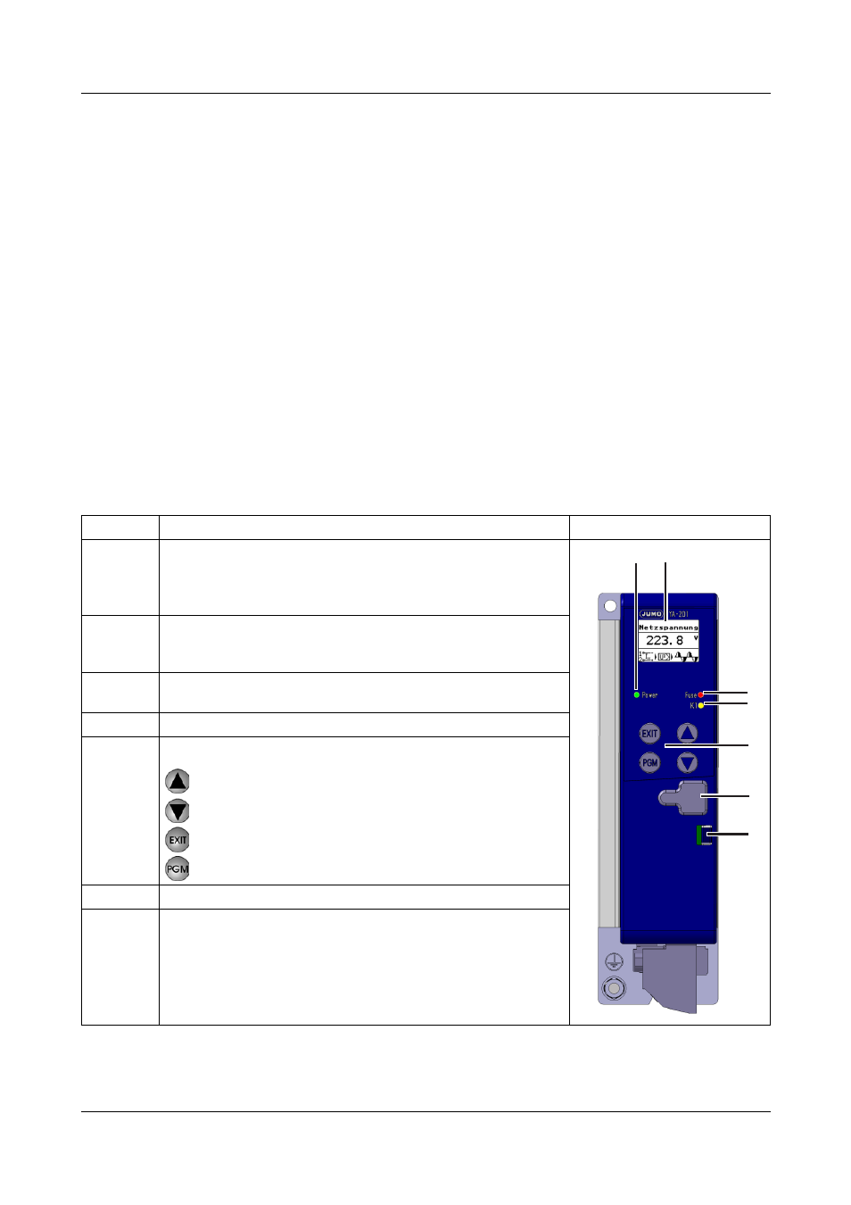
4.1.1 Display and control elements
A
Under no circumstances should the voltage supply for the control elec-
tronics be switched on before the load voltage! This is particularly im-
portant for the operation of transformer loads and resistance loads with
a high temperature coefficient (TC >> 1)!
Legend
Comment
Fig.
1
The Power LED (green) is permanently lit when the voltage sup-
ply is connected.
Flashes at regular intervals if display lighting is switched off.
v Chapter 9 "What to do, if ..."
2
Display (96 x 64 pixels) with white background lighting. The in-
formation line at the bottom of the display shows the current
settings and error messages.
3
Fuse LED (red) is lit in the event of a defective semi-conductor
fuse
4
K1 LED (yellow) fault signal display
5
Keys:
Increase value / previous parameter
Decrease value / next parameter
Abort / one level back
Programing / one level forward
6
USB setup interface
7
Spring clip to release the plastic case
v Chapter 8.2 "Replacing a defective semi-conductor
(1)
(2)
(3)
(4)
(5)
(7)
(6)