INFICON Composer Elite Gas Concentration Monitor User Manual
Page 39
2 - 11
PN
07
4-
56
6-
P1
B
Composer Elite Operating Manual
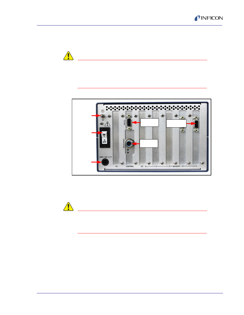
2.2.3 Installing Interconnect, Power Supply, and Communications Cables
1
Set the Sensor Control Unit power switch to 0 (OFF). (See
CAUTION
Composer Elite contains circuitry susceptible to
transient mains voltages. Make certain Composer Elite is
powered down whenever making any interface
connections.
Figure 2-5 Sensor control unit connections
2
Connect the Interconnect Cable(s) male D-sub connector to the Sensor card(s)
connector. (Refer to
.) Tighten the thumb screws on the cable
connector to secure the cable to the Sensor card.
CAUTION
Make certain the Interconnect Cable D-sub connectors
are correctly oriented with the Sensor card / Acoustic
Sensor connectors to avoid damaging connector pins.
3
Connect the Interconnect Cable(s) female D-sub connector to the Acoustic
Sensor(s) connector. Tighten the thumb screws on the cable connector to
secure the cable to the Acoustic Sensor.
4
If applicable, connect the RS-232 cable to the Control card RS-232 connector,
or connect the DeviceNet cable to the Control card DeviceNet connector.
(Refer to
.)
Power
Connector
Power
Switch
Ground
Stud
Sensor Card
Connector
DeviceNet
Connector
RS-232
Connector