2 rated input, 3 power supply environmental specifications, 5 user supplied power supply – INFICON Composer Elite Gas Concentration Monitor User Manual
Page 26
1 - 12
PN
07
4-
56
6-
P1
B
Composer Elite Operating Manual
1.5.4.2 Rated Input
Operational Voltage Range . . . . . . . 100 to 240 V(ac) +/- 10% (ac)
Frequency Range. . . . . . . . . . . . . . . 47 to 63 Hz
In-rush Current . . . . . . . . . . . . . . . . . <60 A at 230 V(ac) input,
25°C ambient cold start
Input Current . . . . . . . . . . . . . . . . . . 2.5 A max.
Overvoltage . . . . . . . . . . . . . . . . . . . 110% - 130% of nominal
(Cycle input power to reset)
Unit Mains Connector. . . . . . . . . . . . IEC320-C14 (Accepts IEC 320-C13)
1.5.4.3 Power Supply Environmental Specifications
Operating Temperature . . . . . . . . . . 0 to +40°C
Storage Temperature . . . . . . . . . . . . -10 to +70°C
Humidity . . . . . . . . . . . . . . . . . . . . . . 20 to 90% non-condensing
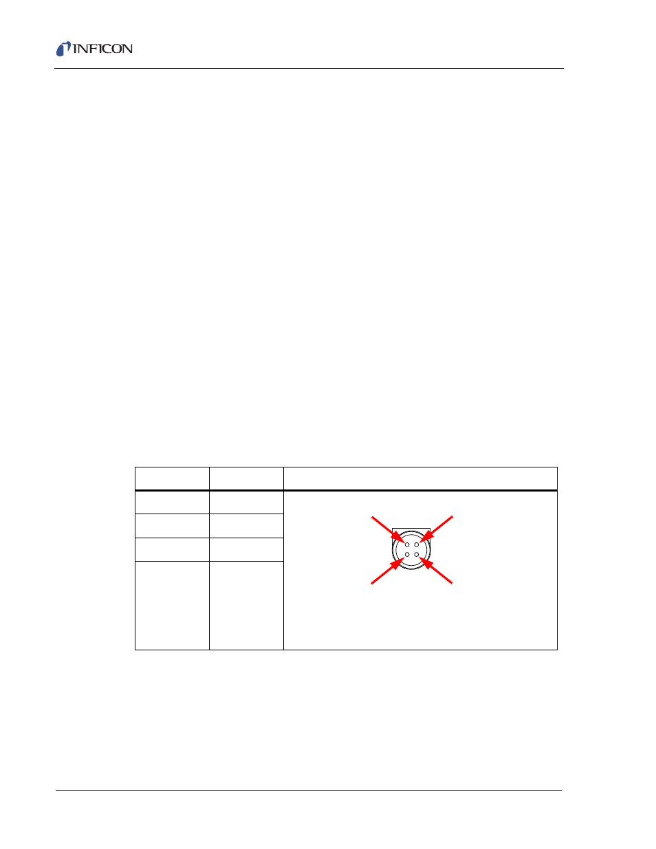
1.5.5 User Supplied Power Supply
If the user provides their own power supply, it must conform to the specifications
and requirements indicated by
. The power supply output cable must
be wired to a 4-pin connector as shown in
Table 1-1 +24 Volt power connector’s pin diagram
Pin
Function
Wiring Diagram for Kycon KPPx-45 Plug
1
Gnd
2
Gnd
3
+24 V
4
+24 V
Pin 1
D.W. (GND)
Pin 2
(GND)
Pin 3
White (+V
o
)
D.W. (GND)
Pin 4
(+V
o
)
4 P POWER DIN