Figure c.4: shmx-4 to stm-100 control cable, Page c- 3 shmx-4 operation – INFICON STM-100/MF Thin Film Deposition Monitor User Manual
Page 99
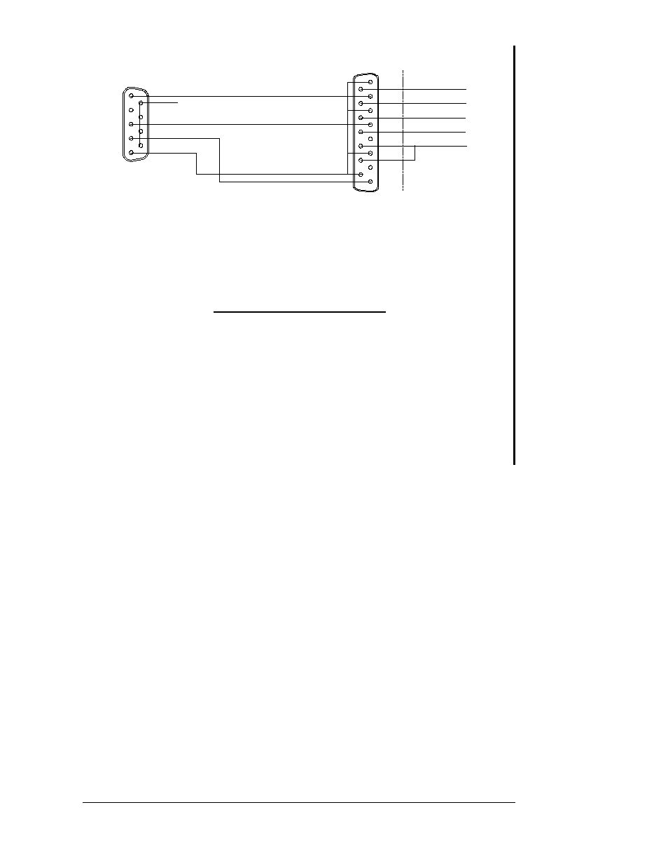
SHMX-4
9 PIN Female
STM-100
5 GND
1 Sensor Fail
3 B Select
4 A Select
Pin 2
Pin 4
Pin 15
Pin 8
Ground
Control Cable, SHMX-4 to STM-100
15 PIN Female
Optional Inputs
Pin 9, Zero Timer
Pin 10, Zero Thickness
Pin 11,Shutter Close
Pin 12, Shutter Open
Pins 13, 14 GND
Pin 1
Pin 3
Pin 7
Pins 1, 3 and 7 tied to pin 15
6 ,7, 8, 9 Internal GND
Channel Select
Input / Output
Figure C.4: SHMX-4 to STM-100 Control Cable
The Optional inputs for opening and closing the shutter and zeroing the
timer and thickness can still be accessed by rewiring the 15 pin connector.
SHMX-4 Relay Output 9 pin D male.
Function
Pins
Sensor 1 Active
1 and 2
Sensor 2 Active
3 and 4
Sensor 3 Active
5 and 6
Sensor 4 Active
7 and 8
GND
9
The Relay Output Connection provides external active channel indication.
The connector pins map as follows. The corresponding relays will open and
close when the active sensor is changed.
Page C- 3
SHMX-4 Operation
- TGF10 Tracer Gas Filler (36 pages)
- Sensistor ILS500 F Leak Detection Filler (90 pages)
- T-Guard Leak Detection Sensor (85 pages)
- T-Guard Leak Detection Sensor Interface description (40 pages)
- Sensistor ISH2000P Hydrogen Leak Detector, Panel Model (51 pages)
- Sensistor ISH2000 HySpeed Hydrogen Leak Detector (54 pages)
- LDS3000 Modular Leak Detector (52 pages)
- LDS3000 Modular Leak Detector Interface description (56 pages)
- BM1000 Bus module (14 pages)
- I/O1000 I/O module (18 pages)
- CU1000 Control unit (24 pages)
- Helium Leak Detector Modul1000 (130 pages)
- Helium Leak Detector Modul1000 Interface description (40 pages)
- UL5000 Dry Helium Leak Detector (108 pages)
- UL5000 Dry Helium Leak Detector Interface description (14 pages)
- UL1000 Fab Dry Helium Leak Detector (119 pages)
- HLD6000 Refrigerant Leak Detector (76 pages)
- HLD6000 Refrigerant Leak Detector Interface Description (40 pages)
- IO1000 I/O module (18 pages)
- Ecotec E3000 Multigas-Sniffer-Leak Detector (92 pages)
- Ecotec E3000 Multigas-Sniffer-Leak Detector Interface description (36 pages)
- Sensistor XRS9012 Hydrogen Leak Detector User Manual (28 pages)
- Sensistor XRS9012 Hydrogen Leak Detector Maintenance manual (14 pages)
- Extrima Ex-certified Hydrogen Leak Detector (62 pages)
- Sensistor ILS500 Leak Detection System (107 pages)
- Sensistor ISH2000 Hydrogen Leak Detector (58 pages)
- Sensistor ISH2000 Hydrogen Leak Detector (108 pages)
- Sensistor Sentrac Hydrogen Leak Detector (86 pages)
- Protec P3000(XL) Helium Leak Detector (132 pages)
- Pilot Plus Vacuum Gauge (2 pages)
- CO Check Carbon Monoxide Meter (2 pages)
- GAS-Mate Combustible Gas Leak Detector (12 pages)
- Whisper Ultrasonic Leak Detector (8 pages)
- Vortex AC Refrigerant Recovery Machine 115V (20 pages)
- Vortex AC Refrigerant Recovery Machine 230V (16 pages)
- Wey-TEK Refrigerant Charging Scale & Optional Charging Module (44 pages)
- Wey-TEK Refrigerant Charging Scale & Optional Charging Module (2 pages)
- D-TEK CO2 Refrigerant Leak Detector (12 pages)
- TEK-Mate Refrigerant Leak Detector (12 pages)
- Compass Refrigerant Leak Detector (12 pages)
- D-TEK Select Refrigerant Leak Detector (12 pages)
- Explorer Portable Gas Chromatograph (369 pages)
- MicroFID II Portable Flame Ionization Detector (89 pages)
- DataFID Portable Flame Ionization Detector for Landfill Emissions Monitoring (91 pages)
- Hydrostik Hydrogen Fuel Cylinder Installation (7 pages)