Figure 6.3: sm75, microdot( connector – INFICON STM-100/MF Thin Film Deposition Monitor User Manual
Page 75
from the 6" BNC cable, and remove the sensor cover and sensing crystal from
the sensing head. Measure the resistance from one of the center push spring
contacts inside the sensor unit to the center conductor of the cable normally
connected to the oscillator. The reading should be less than 0.20
Ω. The
center conductor to the cable shield should be open (greater than 30 M
Ω) with
respect to the outside ground shield of the cable. This check will verify all the
connections from the sensor, the InVac cable, the vacuum feedthrough, and
the BNC cable.
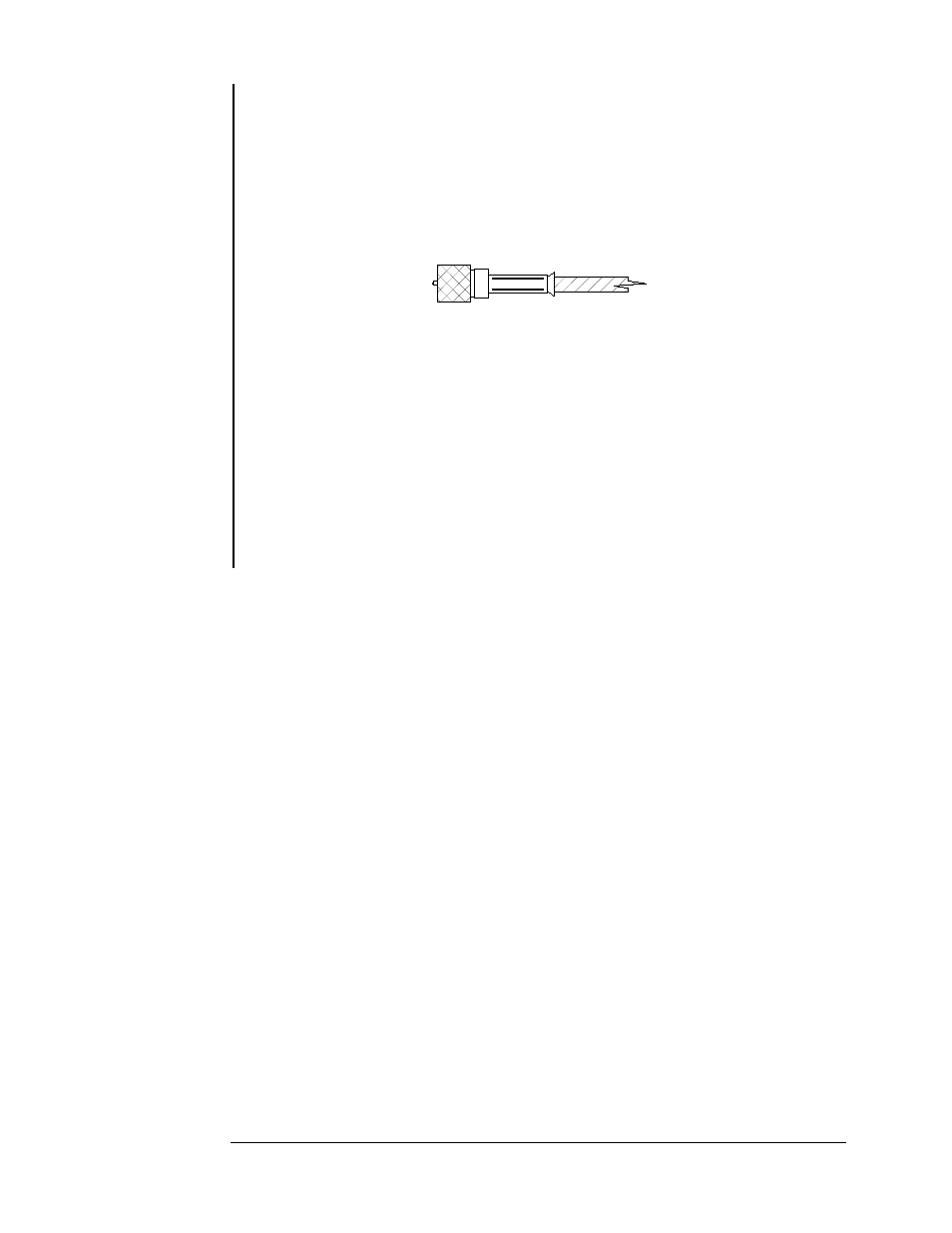
Figure 6.3: SM75, MicroDot
Connector.
If the reading from the continuity test is not as stated, disconnect one part
of the chain and repeat the test. Repeat this last step until the bad connection
is isolated. From experience, most often when a problem occurs it has been
found that the SM75, MicroDot
, connectors on the InVac cable are not
connected securely to the sensor or the feed through. If this is not true then
the cable should be replaced. Also the center pin on the InVac cable can
become damaged and not make contact with the mating connector, Refer to
Figure 6.3. The center pin of the connector should extend slightly beyond the
end of threaded ferrule. If the pin is damaged the cable should be replaced.
MAINTENANCE
Page 6 - 4