Ground, Section 3.3, Grounding – INFICON STM-100/MF Thin Film Deposition Monitor User Manual
Page 36: Figure 3.2: recommended grounding procedure, Connector shielding
proper type for the line voltage chosen. Proper power line cord should be used,
the 110V line cord should not be used for 220V operation.
GROUND
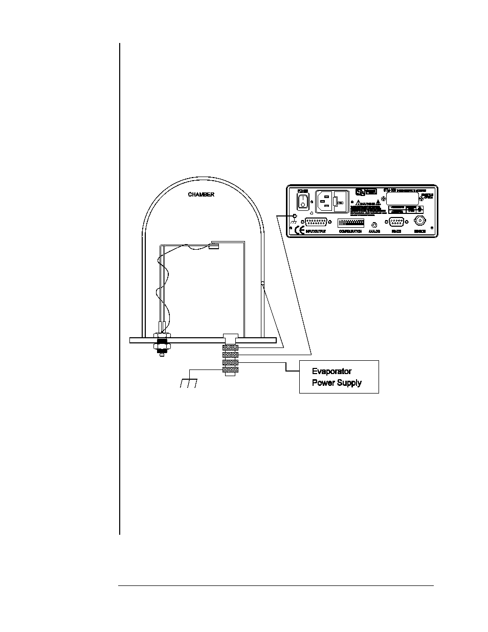
A ground post is provided on the rear panel. This point should be connected
to the DEPOSITION SYSTEM GROUND with the shortest convenient length of
heavy gauge wire. This connection is not required for normal operation but will
make the unit less susceptible to transient noise. See Figure 3.2 for an example
of proper installation.
Figure 3.2: Recommended Grounding Procedure.
CONNECTOR INSTALLATION
In systems with a high noise environment, you need to be careful when
wiring up connectors. A little extra time spent here can save you hours of
frustration later. Sycon provides mating connectors with each instrument. Extra
sets of mating connectors are available from Sycon as part number 514-001. For
best results, use a shielded multi-conductor cable. On the D-connectors, the
metal shells each come with a set of 4 grommets. Pick the grommet for the size
cable that you are using. Cut the outer insulation off of the cable so that it is
exposed to 3/4 of the grommet. Because the grommet is conductive, no additional
shield wiring is needed.
SECTION 3.3
Grounding
Connector Shielding
INSTALLATION
Page 3 - 2