Figure 2.12: tooling parameter, Tooling factor parameter, User configuration switches – INFICON STM-100/MF Thin Film Deposition Monitor User Manual
Page 28: Section 2.5
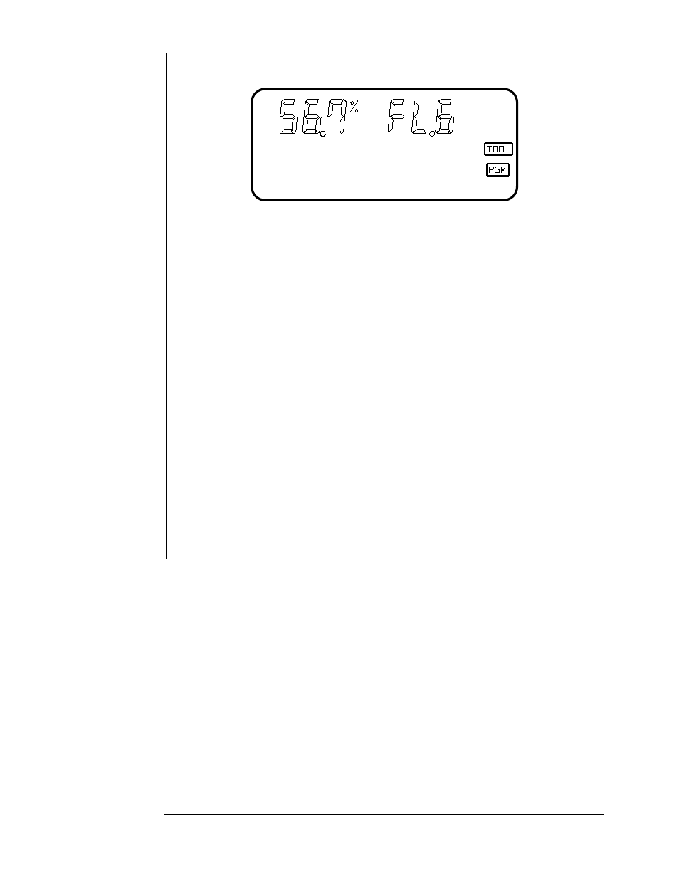
TOOLING
Figure 2.12: Tooling Parameter.
LEGEND
TOOL
RANGE
10.0 to 399
UNITS
PERCENT
The TOOLING parameter is used as a correction factor to compensate
for geometric position differences between the location of the sensor and the
target substrate. Correction is required both the substrate and sensor see the
material source in an identical manner, unless for this case, the Tooling
Parameter is set to 100%. Generally, if the sensor is farther from the source
than the substrate, the tooling will be set to >100%. If the sensor is closer to
the source, the tooling will be set to < 100%. See Section 4.2 for calibration
information.
USER CONFIGURATION SWITCHES
On the rear panel of the STM-100 / MF a twelve selection configuration
switch is located. The settings of this switch allow the user to select various
system operational modes. All communications related variables are also set
here. Switches 1 thru 4 may be changed at any time and will have immediate
effect. Switches 5 thru 12 are only read at the time of power turn on.
Tooling Factor
Parameter
SECTION 2.5
OPERATION AND PROGRAMMING
Page 2 - 8