Sensor connection, Section 3.5, Oscillator connection – INFICON STM-100/MF Thin Film Deposition Monitor User Manual
Page 39: Analog recorder interface, Section 3.6, Analog output specifications, Figure 3.3: recorder output plug
SENSOR CONNECTION
CONNECTION TYPE -- BNC FEMALE
This connection is the REMOTE SENSOR OSCILLATOR interface to the
STM-100 / MF. This connection is both the signal and power path to the oscillator.
The supplied power is 5 volts at 50 mA. The input impedance is 50 ohms and the
signal level is 1 volt peak to peak. The DC voltage may be removed by
disconnecting internal STM-100 / MF jumper J1. This may prove useful if a signal
source other than the Sycon oscillator is utilized. This connection should always
be made with coaxial cable. Type RG58 or RG59 is recommended. Cable lengths
up to 500 feet are acceptable. These cables in 10 and 30 foot lengths are
available as standard parts from Sycon.
ANALOG RECORDER INTERFACE
This connector provides an analog output voltage proportional to either
displayed RATE or THICKNESS as selected by the user option dip switches on the
rear panel of the STM-100 / MF. If SW2 of the user configuration dip switch is set
OFF the analog output will report RATE information. If SW2 is ON, the analog
output will correspond to THICKNESS information. The output voltage is bipolar
and corresponds to the sign of the displayed data.
CONNECTOR TYPE - MINIATURE STEREO SOCKET
CONNECTOR MATE - 1/8 inch Miniature Stereo Jack
SPECIFICATIONS
RESOLUTION .................................. 11 BITS (0.05%)
ACCURACY ..................................... 0.3 % FS
LOADING CAPACITY ...................... 2 mA
F.S. OUTPUT ................................... 10 VOLTS
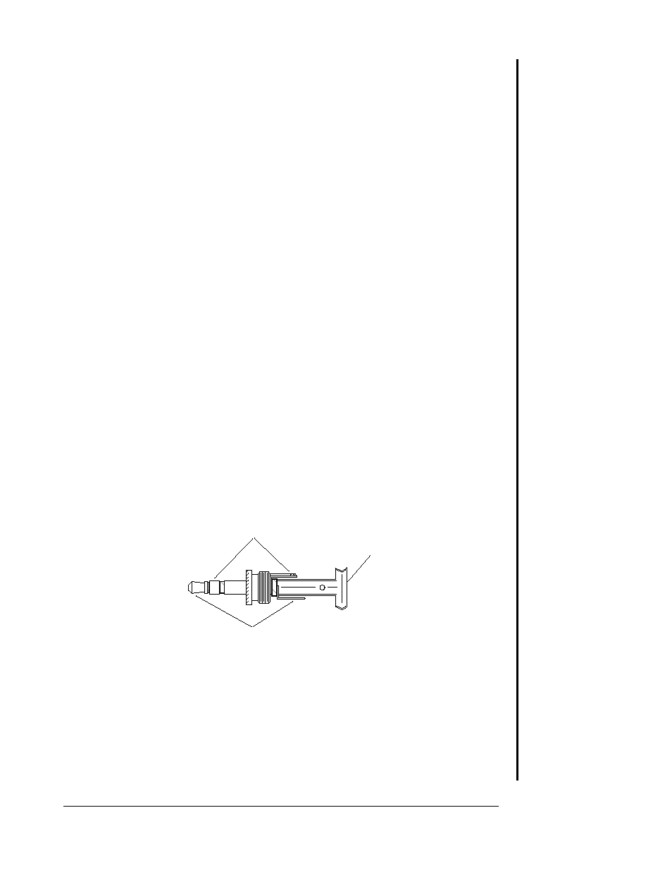
Signal Ground
Shield
Signal
Figure 3.3: Recorder Output Plug.
RECORDER OUTPUT MATING PLUG CONNECTIONS
TIP .................................................. SIGNAL
INSIDE RING ................................... SIGNAL GROUND
OUTSIDE RING ............................... SHIELD
SECTION 3.5
Oscillator Connection
SECTION 3.6
Analog Output
Specifications
Page 3 - 5
INSTALLATION