Heidolph LABOROTA 4000 up to 4003 User Manual
Page 31
Aufstellung und Inbetriebnahme
1.02
Laborota 4000/4001 efficient, 4010/4011 digital, 4002/4003 control
29
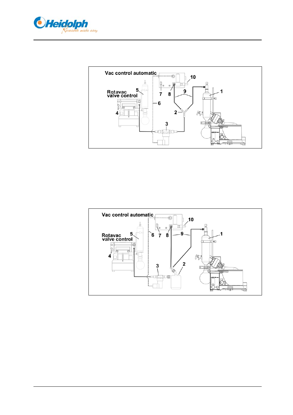
Schlauchführung der einzelnen Vakuumsysteme
Bild 4-17: Laborota 4000/4001 efficient, Laborota 4010/4011 digital mit
Rotavac valve control und Vac control automatic
1 Kühler
6 Kabel
Vakuumventil
2 Y-Stück
7 Netzanschluss
3 Vakuumventil
8 Vakuumanschluss
4 Pumpe Auspuff
9 Vakuumschlauch
5 Kondensatkühler (optional)
10 Belüftung / Schutzgas
Bild 4-18: Laborota 4000/4001 efficient, Laborota 4010/4011 digital mit
Rotavac valve control und Vac control automatic und Woulff’scher
Flasche
1 Kühler
6 Kabel
Vakuumventil
2 Woulff’sche
Flasche
7 Netzanschluss
3 Vakuumventil
8 Vakuumanschluss
4 Pumpe Auspuff
9 Vakuumschlauch
5 Kondensatkühler (optional)
10 Belüftung / Schutzgas
Vakuum-
verbindungen