Control bypass (test mode) – ETC Unison DRd Dimming Rack Enclosure User Manual
Page 58
54
DRd Enclosure Installation Manual
Step 6:
Power up the enclosure. Before installing or removing dimmer or control
modules for service, de-energize main feed to DRd and follow appropriate
Lockout/ Tagout procedures as described in NFPA Standard 70E. It is important
to note that electrical equipment such as dimmer enclosures can present an arc
flash safety hazard if improperly serviced. This is due to available large short
circuit currents on the feeders of the equipment. Any work on energized
equipment must comply with OSHA Electrical Safe Working Practices.
Step 7:
Switch all module circuit breakers to the “On” position.
Step 8:
Reference the related Architectural Control Processor Configuration Manual for
DRd configuration setup and operation.
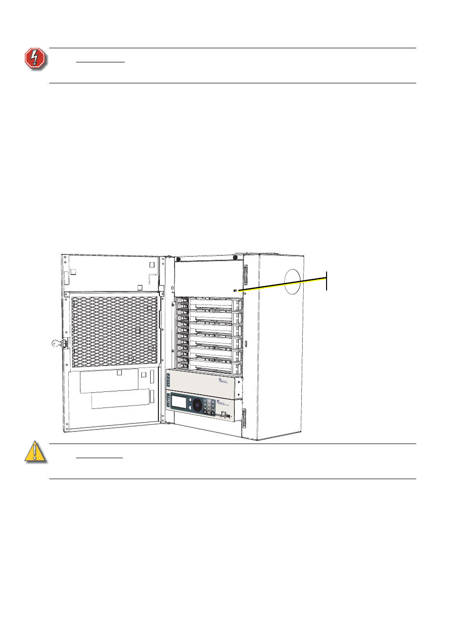
Control Bypass (Test Mode)
Test load circuits connected to the DRd enclosure by switching the “Control Bypass” switch
to the “Test” position. The Control Bypass switch allows testing of lighting loads and
provides temporary lighting before complete system commissioning. Return the switch to
its “Normal” setting after the test is complete.
W A R N I N G :
Never power up or operate the DRd enclosure without all modules installed.
Failure to comply exposes you to dangerously high voltages that may result
in death by electrical shock.
C A U T I O N :
Turning the Control Bypass switch to the “Test” position with all module circuit
breakers “On” will bring all lighting loads to full. To select only certain lighting loads
for test, switch “Off” undesired module circuit breakers in the DRd enclosure.
Control Bypass switch