Dmx control wiring, Ax12x cross-bussed interconnection, N o t e – ETC Unison DRd Dimming Rack Enclosure User Manual
Page 40
36
DRd Enclosure Installation Manual
DMX Control Wiring
DMX wire preparation and termination will vary with the type of wire and termination kit
being used. Please refer to the instructions supplied with the DMX termination kit for
specific wire preparation.
DMX Input Wire Termination using the Screw Terminals
Connector
The graphic to the left illustrates DMX termination layout for the
screw-terminal connectors that are intended for use with Belden
9729 cable (or approved equal) cable type.
Screw terminal connectors are supplied as standard in the DMX
Preparation Kit w/ Screw Connector, part number 4100A1012.
Be aware that cable other than Belden 9729 may have a different
color code for its wire pairs.
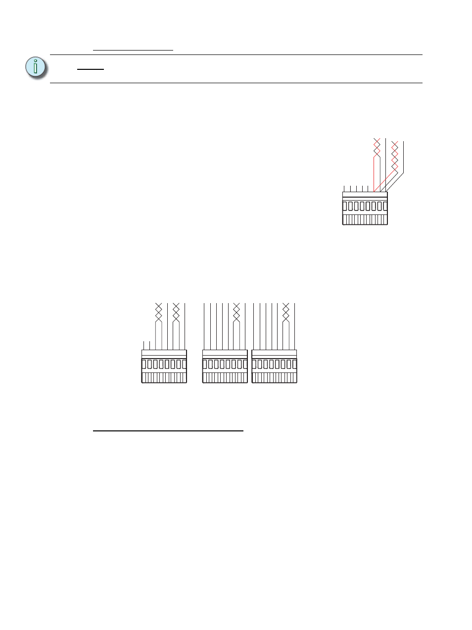
DMX Input Wire Termination using the Insulation
Displacement Connector (IDC)
The graphic below illustrates DMX termination layout for an insulation displacement
connector. This connector type is intended for use with Belden 1583A (or approved equal,
such as Category 5, 5E, or 6) cable type. Be aware that cable other than Category 5 may
have a different color code for its wire pairs.
Reference and follow the DMX Cable Preparation for IDC Termination instruction sheet that
is shipped with the insulation displacement pluggable connector kit (part number
4100A1013).
AX12X Cross-bussed Interconnection
Termination is provided for connection of a second DRd enclosure when installed in a
cross-bussed application. This termination point is labeled “Dual Enclosures” on the right
I/O board.
An interconnect cable is provided which connects enclosure 1, which is the DRd with the
ACP installed, to enclosure 2, which is the secondary enclosure in the cross-bussed
system. This cable is labeled at both ends, one end indicating enclosure 1 and the other
end indicating enclosure 2. You must have installed this cable to the correct enclosure for
proper operation.
This interconnection of enclosures allows full control of both DRd enclosures from only one
Architectural Control Processor installed in rack 1. This may only be used in a cross-bussed
applications.
Reference the Unison Auxiliary Enclosure Installation Manual for instructions to accomplish
this termination.
N o t e :
It is required that you terminate DMX wiring in the same enclosure (rack 1) where
the architectural control processor will be installed.
1
2
3
4
5
6
7
8
COM
n/c
n/c
n/c
n/c
n/c
Data + (Red)
Data - (Black)
From source
DMX A
If daisy-chaining to
another rack or
DMX device...
1
2
3
4
5
6
7
8
n/c
n/c
COM
Data +
Data -
O
RG
W/ORG
W/BRN
COM
Data +
Data -
O
RG
W/ORG
W/BRN
Use the DMX Pass-Thru
connector
If daisy-chaining to
another rack or
DMX device...
DMX A
Thru
DMX B
Thru
1
2
3
4
5
6
7
8
1
2
3
4
5
6
7
8
COM
Data +
Data +
Data -
Data -
O
RG
W/ORG
BRN
GRN
W/GRN
BLU
W/BLU
W/BRN
ORG
W/ORG
BRN
GRN
W/GRN
BLU
W/BLU
W/BRN
COM
From source
DMX A
From source
DMX B