N o t e – ETC Unison DRd Dimming Rack Enclosure User Manual
Page 33
4
Terminate Wiring
29
Step 1:
Route the load wires to the DRd enclosure(s) through the conduit previously
installed.
Step 2:
Prepare the load wires for termination:
a: Label each wire in the set with circuit designation.
b: Separate load circuit wires into ground, neutral and hot/live wire bundles.
Step 3:
Strip 5/8” (16mm) of insulation from the end of each load wire.
Step 4:
Route each load hot/live wire to its individual load output connection.
N o t e :
Plan load wiring appropriately to avoid splicing wiring. Only one load wire per load
terminal.
C A U T I O N :
Dress and terminate wires neatly and avoid leaving extra wire inside the
enclosure. Too much clutter (especially along the right side of the enclosure) can
restrict air circulation and reduce cooling efficiency. If cabling interferes with
airflow during operation, the DRd may be forced to shut down due to overheating.
Load wires should not cross between DRd enclosures. Instead, they should enter
the enclosure in which they will be terminated. Hot/Live and neutral load wiring
must follow the same conduit/path for each circuit.
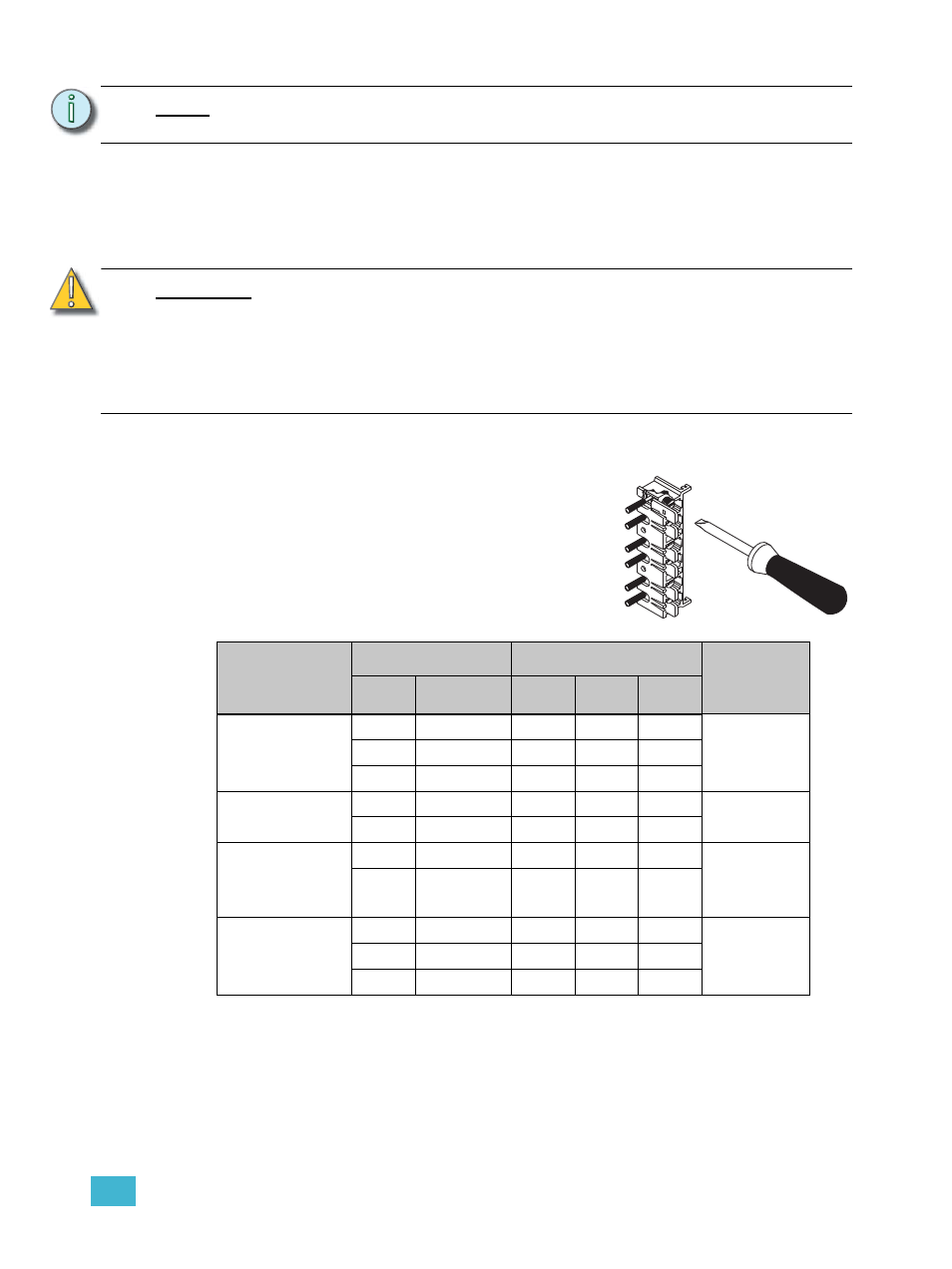
Connection
Cable Size
Torque
Wire Strip
Length
AWG
mm
2
lbf-in
lbf-ft
N - m
15 - 20 amp
load lugs
14 - 10
2.5 - 6
35
2.9
4.0
5/8” - 16mm
8
10
40
3.3
4.5
6 - 4
16
45
3.8
5.1
Ground bus
14 - 8
2.5 - 6
75
6.3
8.5
5/16” - 8mm
6 - 4
16
110
9.2
12.4
Neutral bus
(excluding
230V AC)
14 - 8
2.5 - 6
75
6.3
8.5
5/16” - 8mm
6 - 4
16
110
9.2
12.4
Neutral
Disconnect
(230V AC only)
14 - 10
2.5 - 6
35
2.9
4.0
5/8” - 16mm
8
10
40
3.3
4.5
6 - 4
16
45
3.8
5.1
a: Insert the wire on the back side of the lugs.
b: Torque the lug screw to the recommended
value indicated in the table below.