22 drd enclosure installation manual – ETC Unison DRd Dimming Rack Enclosure User Manual
Page 26
22
DRd Enclosure Installation Manual
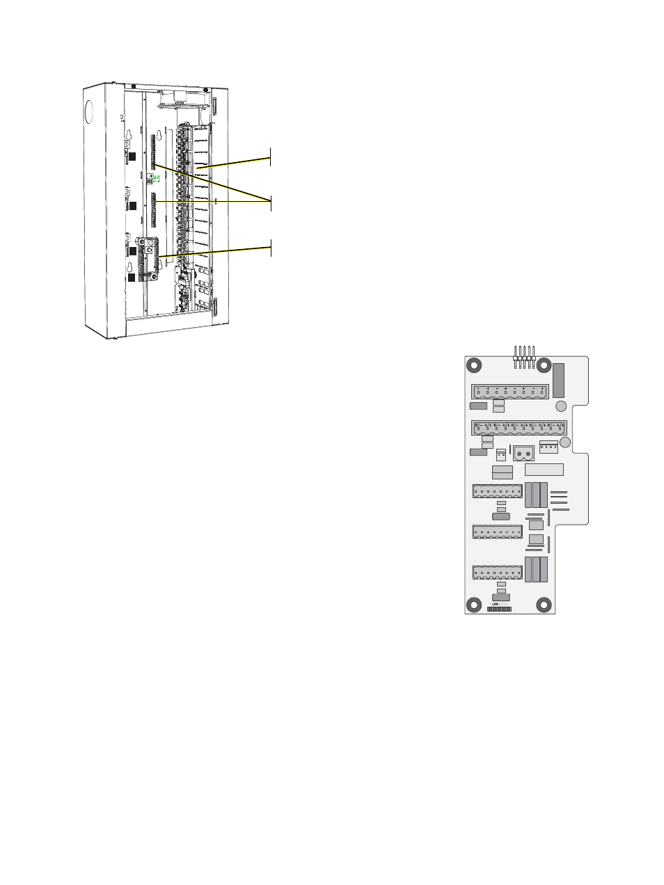
Load circuits terminate to the right side the enclosure.
Load wires terminate to the load lugs on the
right side of the enclosure.
Load neutral and load ground wires terminate
on the neutral and ground bus bars located on
the back panel of the enclosure. An exception
to this is made for the DRd with CE neutral
disconnect. Neutrals are terminated to the
neutral disconnect on the left side of the
enclosure.
See “230V AC Neutral Disconnect
Control wires terminate to the right and left I/O boards in
the DRd enclosure.
Control wires can enter the enclosure from the top, bottom, or
either side, although ETC recommends that you pull control
wires into the enclosure from the bottom since all control
terminations are located near the bottom.
The right I/O board is shipped standard with all DRd
enclosures and includes terminations for:
•
24 vDC Auxiliary Power output connector.
•
LinkConnect/EchoConnect connector.
•
UL 924 emergency contact input for control bypass.
•
Auxiliary enclosure (Dual Enclosure) cross-bussed
interconnection.
•
(2) DMX connections and a DMX pass-through
connection.
•
All option kit connections including DALI, 0-10V, Unison
RideThru option / Unison BatteryPack option.
L1
L2
L3
N
1
2
3
4
5
6
7
8
9
10
11
12
13
14
15
16
17
18
19
20
21
22
23
24
Load Hot / Live
Load Neutral
Load Ground /
Earth
The enclosure door
has been removed
from this graphic for
clarity of this
procedure.
S
IGNAL
D
ISTRO
R
IDE
T
HRU
/B
ATT
J9
DUAL RACKS
LPS
APM
DMXB
AUX POWER
LON LINK / ECHO BUS
CDI
DMXA
B
+
B
-
COM
A
+
A
-
COM
7183B4606
REV
F
© 2013
ETC
,
INC
.
MADE
IN
THE
U
.
S
.
A
.
B
+
B
-
COM
COM
PANIC
A
+
A
-
COM
DMXB
DMXA
SRC
OFF
END
DMX P
ASS
-T
HRU