Connect 0-10v control option wiring, N o t e – ETC Unison DRd Dimming Rack Enclosure User Manual
Page 49
5
Install Option Kits
45
Connect 0-10V Control Option Wiring
To control 0-10V devices, the power circuit in the DRd must be a dimmer or relay module
and assigned to 4-wire fluorescent dimmer mode. Reference the related Architectural
Control Processor configuration manual for instruction to change dimmer mode.
It is important to label the 0-10V load and control wiring sets with the circuit designation.
Control wires terminate on the associated 0-10V option board output terminal. Example: If
circuit 1 is configured as a dimmer with a 4-wire fluorescent dimmer mode, ballast control
wiring would terminate to the 0-10V option board output terminals labeled “1”.
Step 1:
Pull 0-10V control wiring pairs into the DRd enclosure per the wire entry plan.
Step 2:
Strip each wire pair back 1/4 inch (6mm).
Step 3:
Remove the bus connector for outputs 1-6. The pluggable connector is seated
tight in the receptacle. You may need to gently pry the connector free from the
board using a small 3,35mm or 1/8” flat blade screwdriver.
Step 4:
Notice the connector is labeled for your reference during wire termination. Using
a small 3,35mm or 1/8” flat blade screwdriver, loosen the terminals and insert
each of the data “+” and data “–” wires in the wire set into the appropriate
terminal.
a: Terminate the violet (typical) control wire of the first pair into the “+” terminal
associated to the power circuit.
b: Terminate the gray (typical) control wire of the first pair into the “–” terminal
associated to the power circuit.
c: Tighten each screw terminal until the wire is held snug.
Step 5:
Repeat for the remaining outputs through output 6.
Step 6:
Replace the first bus connector to the option board and repeat for the remaining
fluorescent outputs in the system (up to 24 outputs).
N o t e :
0-10V control wiring must be routed in separate conduit from the line voltage
wiring.
N o t e :
The lug number inside the enclosure should match the control line number
designation regardless of whether the DRd is configured for straight or balanced
numbering.
2008
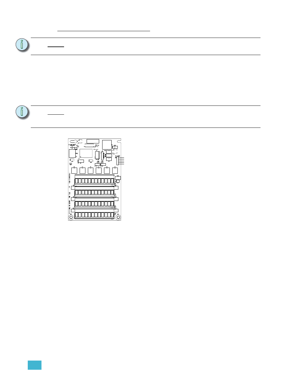
Label
-6+ -5+ -4+ -3+ -2+ -1+
-12+ -11+ -10+ -9+ -8+ -7+
-18+ -17+ -16+ -15+ -14+ -13+
-24+ -23+ -22+ -21+ -20+ -19+
FLUOR 1 - 6
FLUOR 7 - 12
FLUOR 13 - 18
FLUOR 19 -24
Each of the four bus connectors on the option board
provide termination for six fluorescent outputs. Each
bus connector is labeled for ease of identification and is
pluggable for ease of wiring termination. Terminals
accept 12-24 (4 - .25mm
2
) AWG Class 1 wire.