Final installation, N o t e – ETC Unison DRd Dimming Rack Enclosure User Manual
Page 57
6
Final Installation and Power Up
53
Final Installation
.
Step 2:
Reconnect the three cable assemblies to the unit.
a: For the cable bundle on the left side, insert the connector into receptacle until
you hear a click.
b: For the ribbon cable on the right rear side; insert the connector into the
receptacle. Press gently on both sides until it clips into place.
c: For the two-wire cable on the right side, gently press the connector straight
into the receptacle. This connection is also keyed and can only install one
way.
Step 3:
Rotate the access panel closed, then slide the panel up approximately one inch
to align the panel to the captured screws.
Step 4:
Tighten the two captive screws, securing the access panel in place.
Step 5:
Install modules into the DRd.
a: Align each dimmer module with the correct module slot and firmly press into
place. The face of the dimmer module should be flush with the DRd
enclosure.
b: Install the Station Power Module and Architectural Control Processor into
their respective slots. The Architectural Control Processor installs into the
lowest module slot. The Station Power Module installs into the slot directly
above the ACP.
N o t e :
All DRd enclosures are shipped with a dimmer module retention bar installed. The
dimmer module retention bar prohibits installed modules from being removed from
the enclosure without the use of a tool.
Before installing modules into the DRd, loosen the screws retaining this bar in
place, then slide the bar to the left side of the enclosure (door hinge side).
Complete the final installation procedure outlined below, then reengage the
module retention bar (see
). This bar is required to be installed in all
enclosures in order to maintain proper CE rating and NFPA70 compliance.
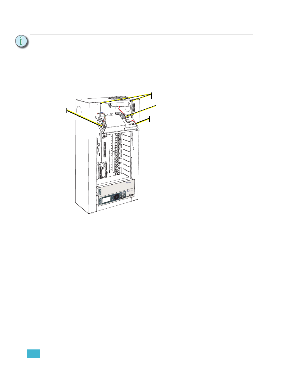
Step 3
Step 2a
Step 2.b
Step 2.c
The enclosure
door has been
removed from
this graphic for
clarity of this
procedure.
Step 1:
Reinstall the Power Supply / Dimming
Engine Access Panel that was
removed prior to conduit installation
and wire termination.
a: Align the guide pins located on the
access panel to the guided slots
on the enclosure.
b: Glide the access panel down, so
that it rests fully into the guided
slots.
c: Tilt the supply access panel away
from the enclosure.