Linkconnect and echoconnect control wiring, Ul 924 listed panic input, N o t e – ETC Unison DRd Dimming Rack Enclosure User Manual
Page 39
4
Terminate Wiring
35
LinkConnect and EchoConnect Control Wiring
Control stations communicate with the Architectural Control Processor using the
LinkConnect or EchoConnect station communication bus from the Architectural Control
Processor to the stations.
Termination is available for up to six home runs of LinkConnect / EchoConnect data runs
utilizing Belden 8471 cable (or approved equal) plus one 14 AWG (2.5mm
2
) ESD drain
wire. This wiring is topology-free and can be installed in any combination of bus, star, loop,
and home run. The total combined length of all wire runs cannot exceed 1,640 feet (500m).
Step 1:
Pull Belden 8471 (approved equal) control wiring and a 14 AWG ground into the
enclosure through the conduit opening previously prepared.
Step 2:
Strip 3/16” (5mm) of insulation from the ends of each wire pair.
Step 3:
Remove the EchoConnect/ LinkConnect (LON) connector from the right I/O
board.
Step 4:
Loosen the terminal screws for as many wire pairs you are terminating.
Step 5:
Insert each white wire (typical) from the pairs into a “B” terminal on the connector
and tighten the screws firmly to secure the wire into the connector.
Step 6:
Insert each black wire (typical) from the pairs into an “A” terminal, next to the
previously installed “B” terminal on the connector and tighten the screws firmly to
secure the wire into the connector.
Step 7:
Terminate the 14 AWG (2.5mm
2
) ground wire to the DRd ground bus bar in the
rear of the enclosure.
Step 8:
Replace the connector to the right I/O board.
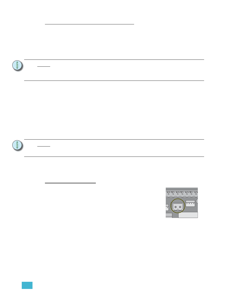
UL 924 Listed Panic Input
Termination is available for a UL 924 Listed dry contact input for
control bypass. The two pin panic connector, labeled “PANIC”,
accepts 16 AWG (1.5mm
2
) wire. Reference the related
Architectural Control Processor Configuration Manual for panic
look setup.
Step 1:
Pull panic wiring into the enclosure through the conduit
opening previously prepared.
Step 2:
Strip 3/16” (5mm) of insulation from the ends of each
wire.
Step 3:
Remove the 2 pin Panic connector from the right I/O board.
Step 4:
Loosen the terminal screws.
Step 5:
Insert each wire into the terminals on the connector and tighten the screws firmly
to secure the wires into the connector.
Step 6:
Replace the connector to the right I/O board.
N o t e :
While the wiring for LinkConnect in SmartLink and Paradigm and EchoConnect for
Echo systems are similar, the communication and control types are not
interchangeable. Each product family requires a dedicated station infrastructure
that cannot be shared.
N o t e :
It is required that you terminate LinkConnect / EchoConnect station wiring and the
auxiliary power wiring in the same enclosure (rack 1) where the station power
module and architectural control processor will be installed.
HRU
/B
ATT
J9
DUAL RACKS
WER /
CDI
COM
PANIC