10v control option kit, Install the 0-10v option kit – ETC Unison DRd Dimming Rack Enclosure User Manual
Page 48
44
DRd Enclosure Installation Manual
0-10V Control Option Kit
Install the 0-10V Option Kit
The 0-10V Control option (DRd-FLO) provides 24 outputs for control of 0-10V (4-wire)
ballasts and drivers. Each channel output is linked one-to-one with a circuit for power
control. The FLO board is comprised of 24 individual 0-10 vDC connections, each rated to
control a maximum of 400mA per channel.
Each output connection is clearly labeled on the removable screw terminal bus connectors.
The removable connectors accept 12 - 24 AWG (4 - .25mm
2
) Class 1 wire.
Step 1:
Align the 0-10V option board to the mounting studs in the bottom of the
enclosure.
•
Notice the mounting holes on the 0-10V option board. One is a slotted
keyhole, another is an open ended slot, and the remaining two on the other
end of the board are standard mounting holes used to secure the board in
place.
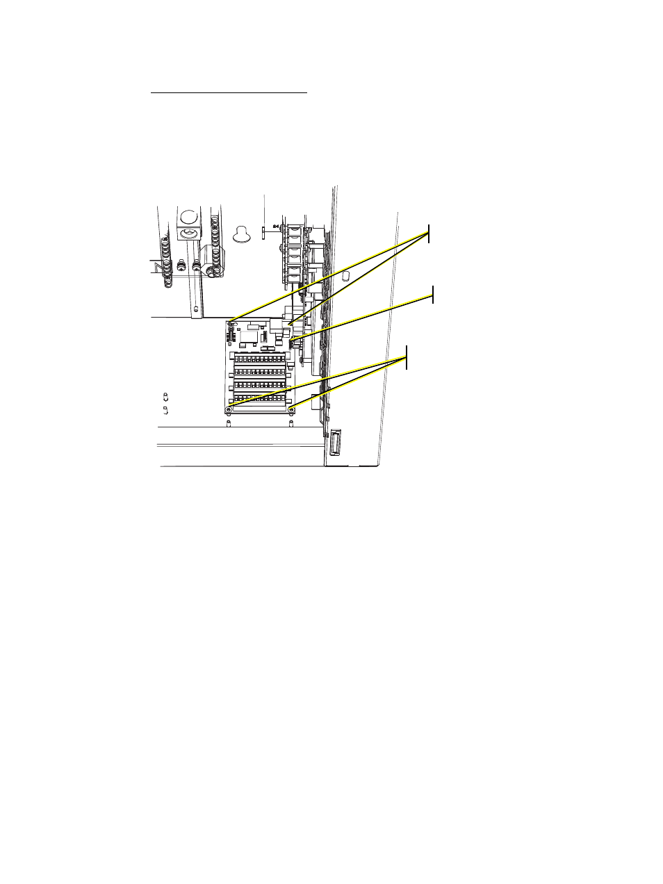
Step 2:
Set the rear left stud through the slotted keyhole and align the open ended slot
with the back right side mounting stud.
Step 3:
Gently slide the option board toward the right I/O board aligning the five prong
connector to the receptacle on the I/O board.
Step 4:
Secure the remaining two mounting holes to the pems with the screws provided.
Step 2
Step 3
Step 4