Wire fluorescent, N o t e – ETC Unison DRd Dimming Rack Enclosure User Manual
Page 36
32
DRd Enclosure Installation Manual
shown in the graphic above. Torque the wire to the recommended value in the
torque table above.
Step 5:
Strip the neutral wire to the length indicated in the table above and terminate to
the neutral terminal assembly. Torque to the recommended value also indicated
in the table above.
Step 6:
Strip the ground/earth wires to the length indicated in the table above and
terminate to the ground bus terminal. Torque to the recommended value also
indicated in the table above.
2-wire Fluorescent
To control 2-wire fluorescent ballasts, the power circuit in the enclosure must be configured
as a standard module type (D15, D20, AD15, AD20, ED15, ED25, HD15, HD25) with a 2/
3 wire fluorescent dimmer mode assignment. Reference the related Architectural Control
Processor Configuration Guide for instruction to change dimmer mode.
Step 1:
Pull fluorescent ballast power wiring into the DRd enclosure per the wire entry
plan.
Step 2:
Strip 5/8” (16mm) of insulation from the end of each load wire.
Step 3:
Terminate the load wire (typically black) to the assigned dimmer lug by inserting
wire between the back of the lug and the pressure plate.
a: Insert the wire on the back side of the lugs.
b: Torque the lug screw to the recommended value indicated in the table below.
Step 4:
Strip the neutral wire to the length indicated in the table above and terminate to
the neutral terminal assembly. Torque to the recommended value also indicated
in the table above.
Step 5:
Strip the ground/earth wires to the length indicated in the table above and
terminate to the ground bus terminal. Torque to the recommended value also
indicated in the table above.
N o t e :
Ground connections must use all metal nuts and lock washers.
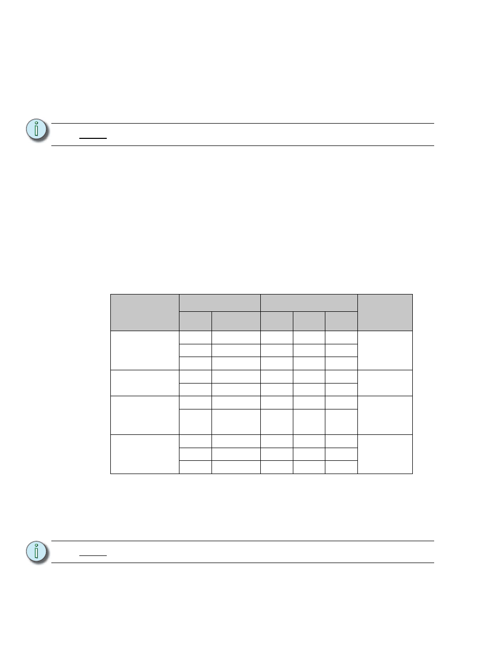
Connection
Cable Size
Torque
Wire Strip
Length
AWG
mm
2
lbf-in
lbf-ft
N - m
15 - 20 amp
load lugs
14 - 10
2.5 - 6
35
2.9
4.0
5/8” - 16mm
8
10
40
3.3
4.5
6 - 4
16
45
3.8
5.1
Ground bus
14 - 8
2.5 -6
75
6.3
8.5
5/16” - 8mm
6 - 4
10
110
9.2
12.4
Neutral bus
(excluding
230V AC)
14 - 8
2.5 -6
75
6.3
8.5
5/16” - 8mm
6 - 4
10
110
9.2
12.4
Neutral
Disconnect
(230V AC only)
14 - 10
2.5 - 6
35
2.9
4.0
5/8” - 16mm
8
10
40
3.3
4.5
6 - 4
16
45
3.8
5.1
N o t e :
Ground connections must use all metal nuts and lock washers.