Terminate auxiliary power, N o t e – ETC Unison ERn Wall-mount Control Enclosure User Manual
Page 24
20
Unison
®
ERn Wall Mount Enclosure Installation Manual
Step 2:
Strip 3/16” (5mm) if insulation from the ends of each wire pair.
Step 3:
Remove the LinkPower connector (labeled LON) from the right I/O board.
Step 4:
Loosen the terminal screws for as many wire pairs you are terminating.
Step 5:
Insert each white wire from the pairs into an “A” terminal on the connector and
tighten the screw firmly to secure the wire into the connector.
Step 6:
Insert each black wire from the pairs into an “B” terminal on the connector and
tighten the screw firmly to secure the wire into the connector.
Step 7:
The 14 AWG (2.5mm
2
) ground wire can terminate to the ground bus located
inside the ERn enclosure.
• If grounded metal conduit is installed a ground wire may not be required for
termination. Reference the related
station installation manual
for details.
Step 8:
Replace the connector to the right I/O board.
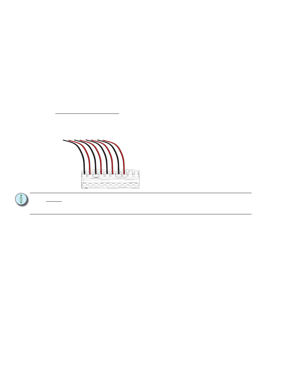
Terminate Auxiliary Power
The auxiliary power connector (labeled Aux Power) provides termination for up to 20 wires
in the ten position pluggable connector. Each terminal allows up to two 16 AWG(1.5mm
2
)
wire and provides 24 Vdc power to Unison control stations when used with the Paradigm
ACP.
Step 1:
Pull auxiliary control power wiring (typically 16 AWG (1.5mm
2
) red / black wire
pair) into the ERn enclosure through the conduit opening previously prepared.
Step 2:
Strip 3/16” (5mm) of insulation from the ends of each wire pair.
Step 3:
Remove the auxiliary power connector from the right I/O board.
Step 4:
Loosen the terminal screws for as many auxiliary wire pairs as you are
terminating.
Step 5:
Insert the black auxiliary power wire from the pair into a “-” terminal on the
connector and tighten the screw to secure the wire into the connector.
Step 6:
Insert the red auxiliary power wire from the pair into a “+” terminal on the
connectors and tighten the screw to secure the wire into the connector.
Step 7:
Repeat steps 5 and 6 for all auxiliary power wires in the rack.
Step 8:
Replace the connector on the right I/O board.
N o t e :
It is required that you terminate LinkPower station wiring and the auxiliary power
wiring to the ERn enclosure I/O board that will host the Paradigm Station Power
Module (P-SPM).
- + - + - + - + - +