Det-Tronics EagleVision - PC User Manual
Page 98
From the Point Configuration screen, highlight the logic controller, then
click on the Display Point button. The Logic Controller Point Display
screen will be displayed. Click on the Diagnostics button. The Logic
Controller Diagnostics screen will be displayed. A tabbed notebook is
displayed at the top of the screen.
LC NV S
TATUS
W
ORDS
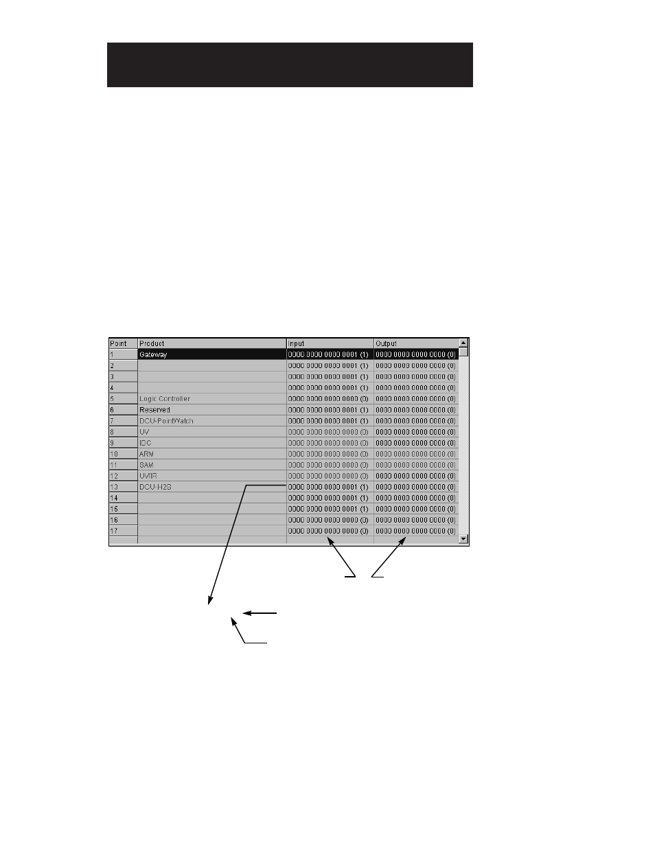
Click on the LC NV Status Words tab to display the Logic Controller
Network Variable Status Words screen. See Figure X–1. This display
shows the raw alarm message data entering and leaving the logic con-
troller. The alarm messages consist of 16 bit words with some bits pre-
defined, while others have special meaning depending on the device
type.
C
ARDS
D
ETECTED
Click on the Cards Detected tab to display the LIOU Cards Detected
screen. See Figure X–2. During configuration a list of LIOU boards is
generated. On power-up the logic controller polls all available board
addresses, establishing a list of “detected boards”. The logic controller
then compares the list of detected boards with the list of configured
boards. If extra boards are found, the IO Board Count fault bit is set. If
any boards are missing, the IO Not Communicating fault bit is set.
95-8479
10.1
L
OGIC
C
ONTROLLER
D
IAGNOSTICS
Information Leaving the Controller
Information Entering the Controller
0000 0000 0000 0000 (0)
Binary Information
Decimal Equivalent
Not Communicating Bit
FIGURE X-1
Logic Controller Network
Variable Status Words