Det-Tronics EagleVision - PC User Manual
Page 92
R
ESET
B
UTTON
This button resets the communication module’s output relay.
F
ETCH
L
OGS
B
UTTON
This button will retrieve the alarm logs.
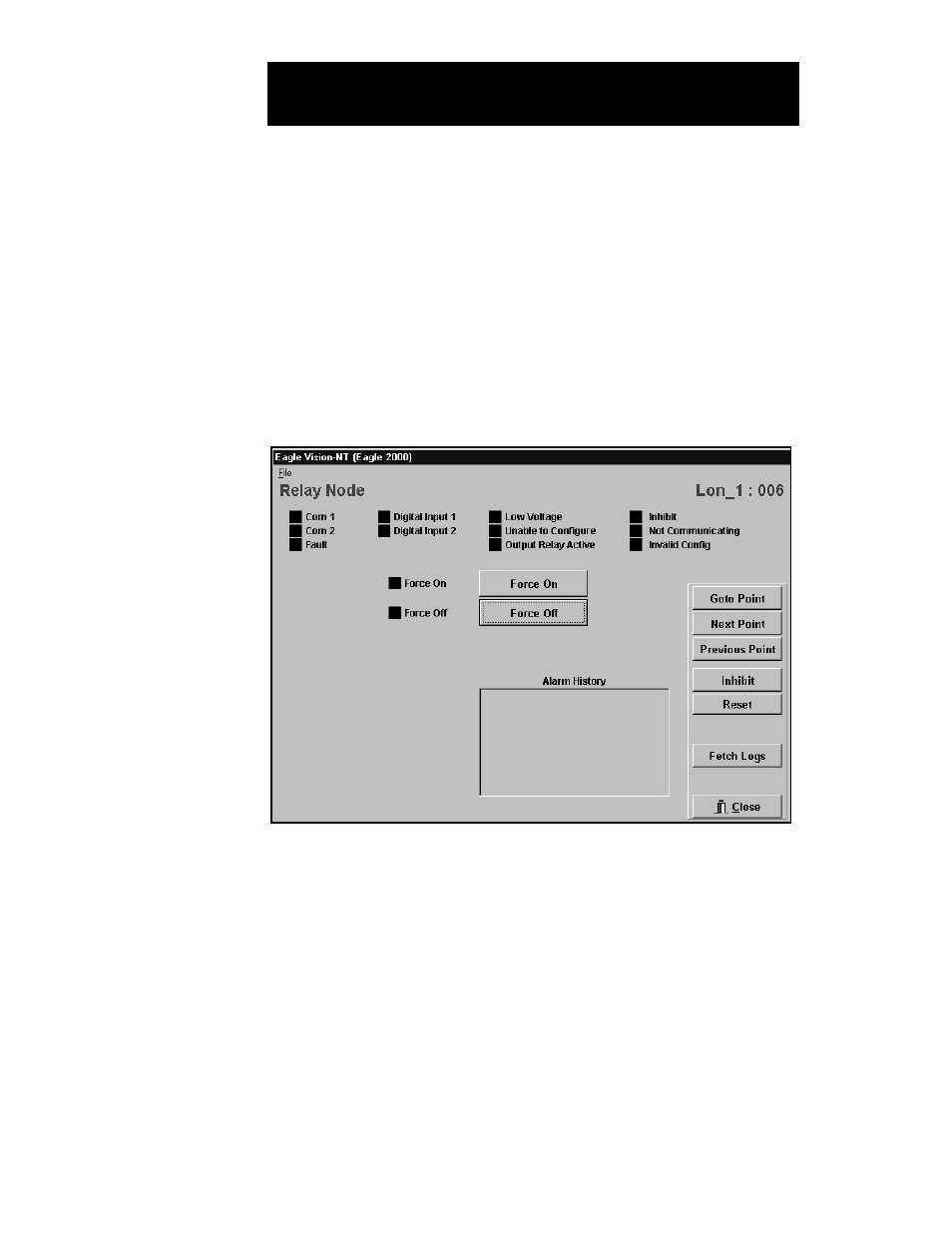
From the Point Configuration screen, highlight the relay node, then click
on Display Point or select Point from the View menu. The Relay Node
Point Display screen will be displayed. See Figure VIII–3.
S
TATUS
I
NDICATORS
Com 1 and Com 2. One of these bits is set when the relay node’s
fault isolation circuitry has detected and isolated a wiring fault.
Fault. This bit is set when the internal fault detection circuitry has indi-
cated a hardware fault.
Digital Input 1/2. These indicators show the status of the signals con-
nected to the relay node’s two digital inputs.
8.6
E
AGLE
2000 P
OINT
D
ISPLAYS
R
ELAY
N
ODE
P
OINT
D
ISPLAY
FIGURE VIII-3
Relay Node
Point Display Screen