Lon t – Det-Tronics EagleVision - PC User Manual
Page 97
NOTE
Since the logic controller occupies an address on the LON, the
relay contacts must close during a fault condition to ensure normal
communication until the fault can be repaired. Closing the con-
tacts allows messages from the downstream side of the wiring
fault to pass through the gateway and reach the logic controller.
As a result, messages will continue to be received by both gate-
way transceivers.
By opening the contacts using the LON Override button, each node is
able to report to only one side of the gateway. All nodes on one side of
the fault will be blue and all nodes on the other side will be green, with
the wiring fault located between the last green node and the first blue
node.
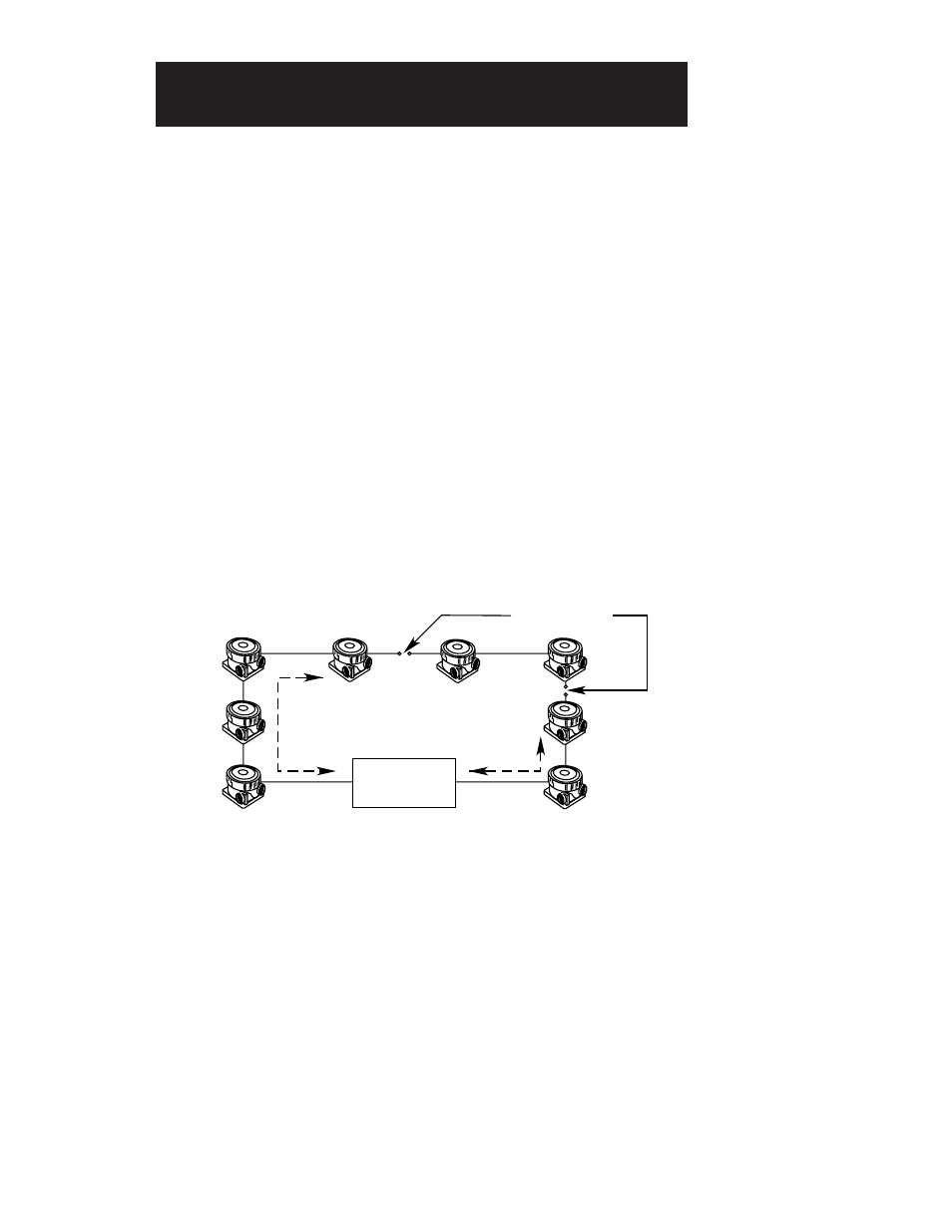
In the event of multiple wiring faults on the LON, as shown in Figure IX-
4, those nodes between the faults are unable to communicate with the
gateway. In this case, all nodes between the faults will be red in color,
while the nodes on one side of the fault will be blue and the nodes on
the other side will be green.
When troubleshooting is complete, click on the LON Override button to
return the gateway relay to normal operation.
IMPORTANT
Incorrect network communication can occur if the gateway relay
is inadvertently left in the LON Override position.
Click on the Network button to return to the Point Configuration screen.
95-8479
9.3
LON T
ROUBLESHOOTING
A1853
LCU
NODE 1
NODE 8
NODE 3
NODE 6
NODE 2
NODE 7
NODE 4
NODE 5
PATH A
PATH B
WIRING FAULTS
FIGURE IX-4
Communication with Multiple
Wiring Faults on the Network