Det-Tronics EagleVision - PC User Manual
Page 68
User Switches — these bits track the status of the local digital inputs.
NV Output Failed — logic controller was unable to communicate
with a LON output device like a SAM or ARM.
P
ROCESS
V
ARIABLE
D
ISPLAY
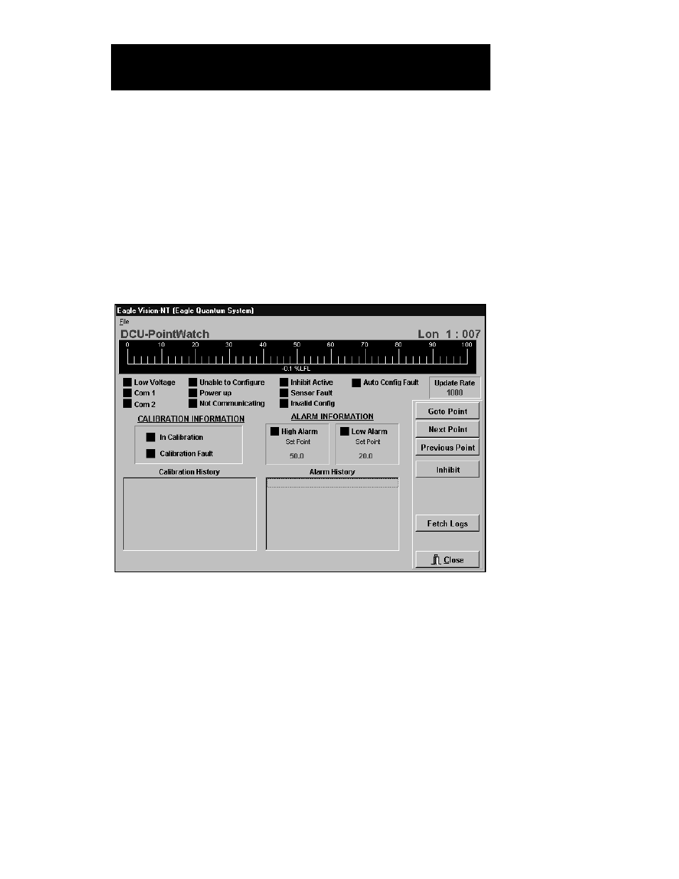
The gas level / process variable is graphically displayed on an analog
bar graph. See Figure VII–8. The scaling and engineering units will
change depending on the type of gas and configuration settings.
S
TATUS
I
NDICATORS
Low Voltage. This bit is set when the input power voltage to the DCU
is below 17.5 volts. The actual voltage can be read from the “Network”
screen. The typical cause of this fault is under-sized wire.
Com 1 and Com 2. One of these bits is set when the DCU’s fault iso-
lation circuitry has detected and isolated a wiring fault.
Unable to Configure. This bit is set by the gateway when it is unable
to successfully transfer configuration information to the DCU.
Power up. This bit is set during the power-up time delay.
95-8479
7.11
E
AGLE
Q
UANTUM
P
OINT
D
ISPLAYS
DCU P
OINT
D
ISPLAY
FIGURE VII-8
DCU Point Display Screen