Det-Tronics EagleVision - PC User Manual
Page 21
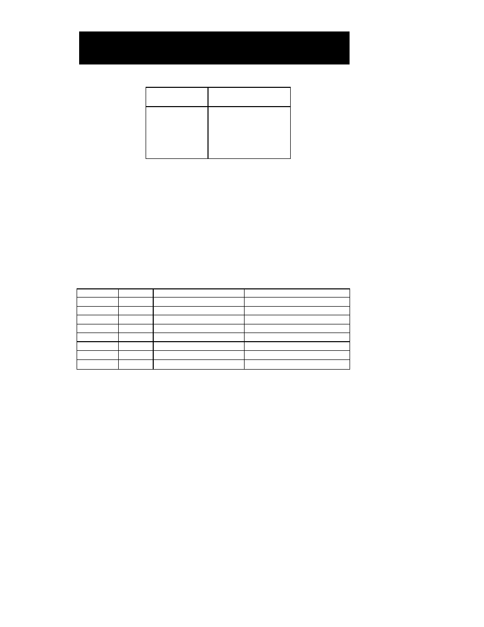
The “Word Range Write” function will not call control word func-
tions. The “Read Modify Write” or “Typed Write” functions must be
used for control words. N:20 and 21 are the default file numbers,
and can be changed by entering the desired file number in the AB
File No. field under Port 1 Config on the Gateway Configuration
screen. The lowest file number (N:20) can be changed in the gate-
way configuration while the second file number is always one high-
er.
Refer to Table V-2 for the Allen Bradley memory map.
Modbus RTU Mode
When Modbus mode is used, the gateway is the slave device.
Port 2. Port 2 of the Gateway can be configured for either Modbus
master or slave operation.
As a Modbus RTU master, it actively “feeds” a copy of its datatables
to a slave PLC. When set for the master mode, enter the PLC address
in the Modbus Address field under Port 2 Config.
When set for the slave mode, enter the gateway address in the
Modbus Address field. (The address in the Modbus Address field
should be the address of the slave device.)
The Master Data Offset specifies where in the slave PLC’s register
memory (40,000 registers) the data from the Eagle system will
begin.
95-8479
5.5
E
AGLE
Q
UANTUM
S
YSTEM
C
ONFIGURATION
AB Function
Definition
Number
0
Word Range Write
1
Word Range Read
26H
Read Modify Write
67H
Typed Write
68H
Typed Read
TABLE V-1
Functions Supported
by EagleVision-NT
File Number
Element
Memory Block
Access
N:21
0 to 499
A Configuration
Read / Write (Non-Volatile)
N:20
500 to 749
B Control Words
Read / Write (Gateway will clear the bit)
N/A
C-1 Extended Gateway Status
Read Only
N:20
0 to 249
C-2 Status Words
Read Only
N:20
250 to 499
D Process Variable
Read Only
N:20
750 to 874
E-1 Transfer Buffer from Gateway
Read Only
N:20
875 to 999
E-2 Transfer Buffer to Gateway
Read / Write
N:21
500 to 515
F Last Direction Data
Read Only
TABLE V-2
Allen Bradley
Memory Map