Det-Tronics EagleVision - PC User Manual
Page 25
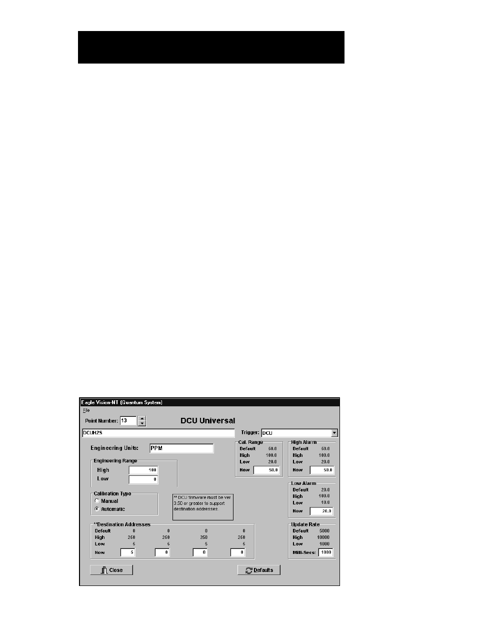
7. Enter the Destination Address(s). The Destination Address is the
address of the Logic Controller that will receive messages from this
DCU. If the DCU will report to more than one Logic Controller, an
address for each Logic Controller (up to a maximum of four) must be
entered.
Since Logic Controllers occupy two addresses, they are able to
receive messages at either address. (Do not program a single point
to report to both addresses.) To maximize system speed and per-
formance, it is recommended to alternate odd and even addresses
during system configuration — i.e. half of the field devices report to
the odd address and the other half report to the even address. A
convenient way to do this is to have odd numbered field devices
report to the Logic Controller at its odd address and even numbered
devices at the even address. (Failure to alternate odd and even des-
tination addresses will not compromise system communication.)
8. Click on Accept. Click on Close to exit and return to the Point
Configuration screen, or use the scroll arrows to select the next point
for configuration.
To configure a Universal DCU:
1. Highlight the desired address on the Point Configuration screen.
Click on the Modify Point button.
2. Click on the Define button.
3. Click on the DCU Universal button, then click on OK. The DCU
Universal Configuration screen will be displayed. See Figure V–6.
95-8479
5.9
E
AGLE
Q
UANTUM
S
YSTEM
C
ONFIGURATION
FIGURE V-6
DCU Universal
Configuration Screen