Det-Tronics EagleVision - PC User Manual
Page 36
3. Click on the appropriate button for the number of power supplies
being used.
4. Click on OK to return to the Logic Controller Configuration screen.
5. Repeat for each power supply in the LIOU.
The Logic Controller must be configured to look for messages from spe-
cific addresses on the network and to ignore the remaining addresses.
All devices reporting to the logic controller must be included.
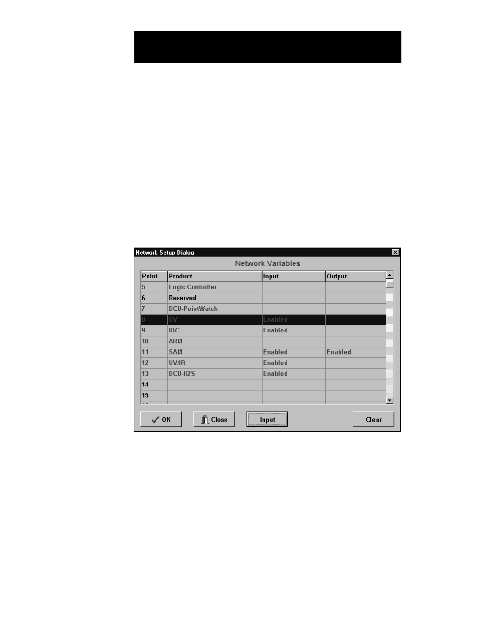
1. Click on the Network Setup button. The Network Variables screen is
displayed. See Figure V–16.
2. The points that can communicate with the Logic Controller (IDCs, UV
detectors, SAMs, ARMs, other Logic Controllers) are listed in red,
the others in black. Highlight the first red point. To enable the point,
click on the appropriate Input or Output button. To disable a point,
click on Clear. If a regular message is not received from an enabled
address, the NV Communicating trouble bit will be set.
Depending upon the type of device and its function within the sys-
tem, this procedure can involve input, output or both. The software
will automatically select the appropriate function(s).
5.20
E
AGLE
Q
UANTUM
S
YSTEM
C
ONFIGURATION
NV (N
ETWORK
V
ARIABLE
)
C
ONFIGURATION
FIGURE V-16
Network Variables Screen