Det-Tronics EagleVision - PC User Manual
Page 72
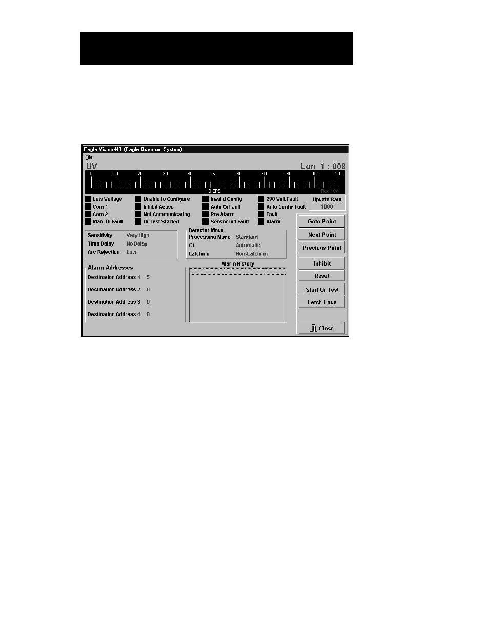
From the Point Configuration screen, highlight the UV Flame Detector,
then click on Display Point or select Point from the View menu. The UV
Flame Detector Point Display screen will be displayed. See Figure
VII–10.
B
AR
G
RAPH
D
ISPLAY
The bar graph shows the current UV signal in counts per second (cps).
Two scales are displayed, a blue bar shows the signal level from 0 to
100 cps and a red bar is 10 times the scale (0 to 1000 cps). In normal
operation, the signal should read zero. When an automatic Oi (optical
integrity) test is performed, a small signal level is visible. A signal is also
visible when a manual Oi test is performed or when an external UV
source is detected.
S
TATUS
I
NDICATORS
Low Voltage. This indicator turns on when the input power voltage to
the UV flame detector is below 17.5 volts.
Com 1 and Com 2. One of these bits is set when the fault isolation
circuitry in the UV detector has detected and isolated a LON wiring
fault.
Manual Oi Fault. This indicator turns on when the UV detector fails
a manually initiated Oi test.
95-8479
7.15
E
AGLE
Q
UANTUM
P
OINT
D
ISPLAYS
UV F
LAME
D
ETECTOR
P
OINT
D
ISPLAY
FIGURE VII-10
UV Flame Detector
Point Display Screen