Led indicator connection, Induction loop connection – 2N Lift8 v1.5.2 User Manual
Page 45
45
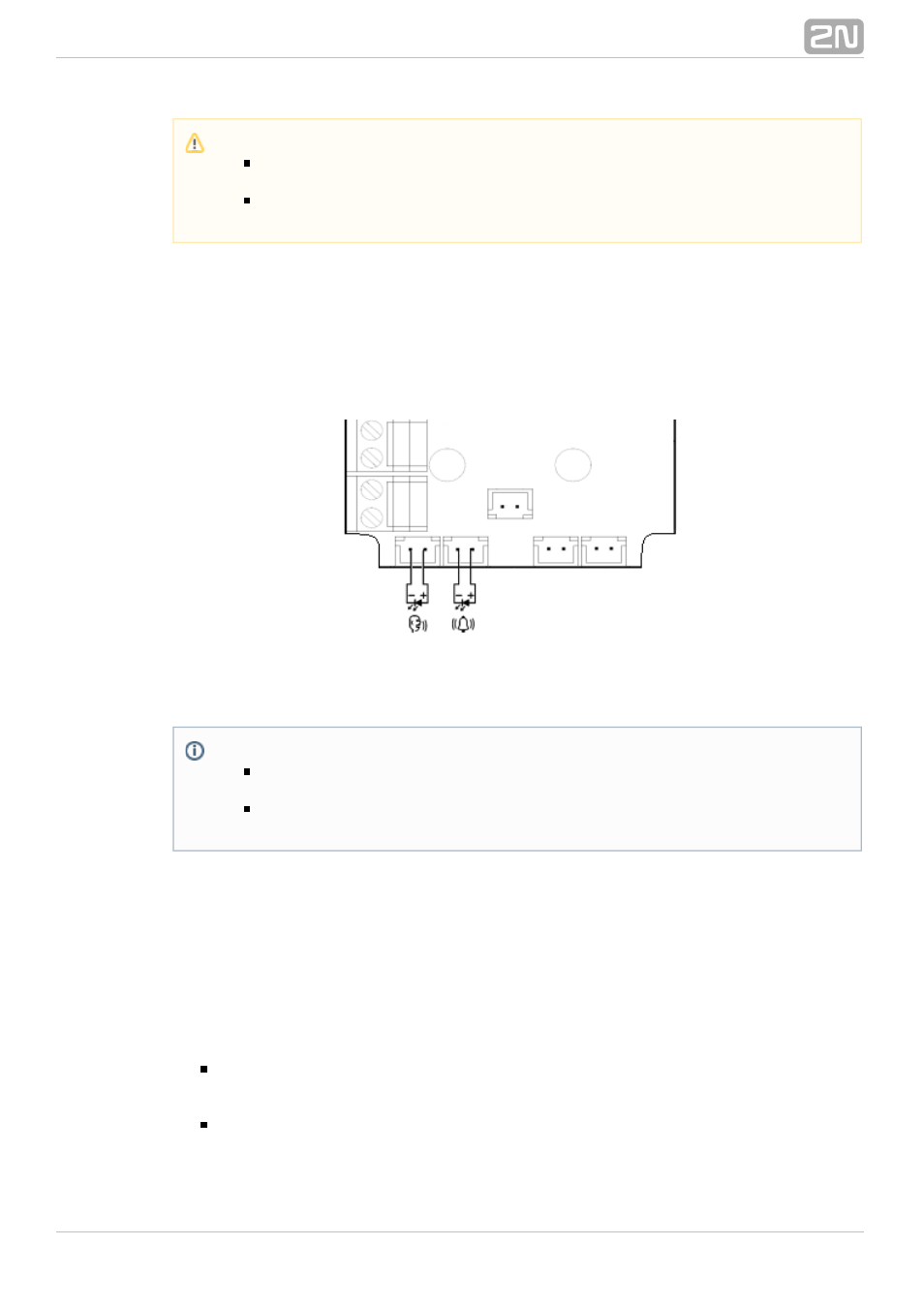
LED Indicator Connection
The current LED technology makes it possible to achieve a relatively good light
intensity with a small current. If the lift indicators are illuminated with a sufficiently
efficient LED requiring a current of approx. 5 mA (with diode loss of about 2 V), no
power supply is needed. See the figure below for the connection.
Figure: Alternative LED Connection for Audio Unit – Cabin Universal
Induction Loop Connection
The regulations that apply to communicator installations may require a mandatory loop
for persons with defective hearing in the lift cabin. In that case, connect the loop to
connector (10) with any polarity. The loop including a 1m long cable can be part of
your delivery if agreed so.
Requirements
The induction loop has to be placed behind a non-metal, non-magnetic cover in
the control panel as the magnetic field of the induction loop cannot go through a
metal control panel.
The induction loop has to be labelled with an appropriate symbol (ear) placed
according to the applicable standards.
Caution
Remember to program delayed calling to make the CANCEL connection
work successfully.
Refer to the electronics cover for the ALARM and CANCEL configuration
scheme.
Note
The cables required for this configuration are not part of the standard
delivery but are available upon agreement.
In this configuration, the auxiliary indicators on the PCB are not
illuminated.