6 drive motor, Description, Shaft seal replacement – JLG 450A_AJ Series II Service Manual User Manual
Page 97: Drive motor -47, Description -47 shaft seal replacement -47, Drive motor cross section -47, Removing shaft seal -47
SECTION 3 - CHASSIS & TURNTABLE
3121180
– JLG Lift –
3-47
3.6 DRIVE MOTOR
NOTE: This procedure covers:
2WD motors used on GM powered machines.
2WD motors used on Caterpillar, Deutz, and Ford
powered machines S/N 0300100514 to Present.
All 4WD motors.
Description
Drive motors are low to medium power, two-position axial
piston motors incorporating an integral servo piston. They
are designed for operation in open and closed circuit
applications. The standard control is a direct acting single
line hydraulic control. The integral servo piston controls
motor displacement.
Motors are spring biased to maximum displacement and
hydraulically shifted to minimum displacement. Minimum
and maximum displacement can be set with fixed internal
stops. The large diameter servo piston allows smooth
acceleration and deceleration with relatively large circuit
orificing.
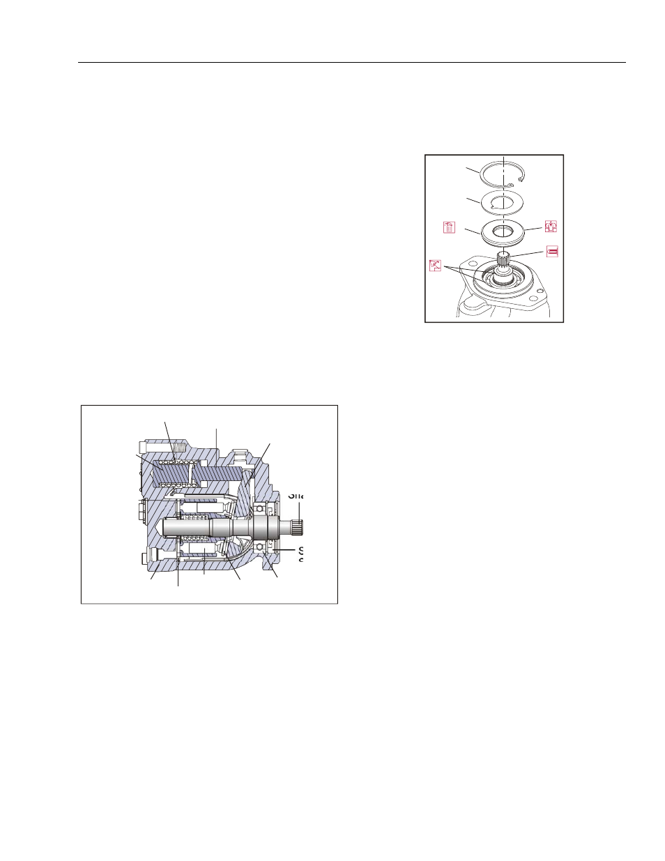
Shaft Seal Replacement
REMOVAL
1. Remove snap ring (1) and support washer (2).
NOTE: To avoid damaging shaft during removal, install a
large sheet metal screw into chuck of a slide ham-
mer. Drive screw into seal surface and use slide
hammer to pull seal.
2. Carefully pry out and discard shaft seal (3).
INSPECT COMPONENTS
Inspect new seal, motor housing seal bore, and sealing
area on shaft for rust, wear, and contamination. Polish
shaft and clean housing if necessary.
INSTALLATION
1. Cover shaft splines with an installation sleeve to pro-
tect shaft seal during installation.
2. Install a new shaft seal (3) with cupped side facing
motor. Press seal into housing until it bottoms out.
Press evenly to avoid binding and damaging seal.
3. Install seal support washer (2).
4. Install snap ring (1).
5. Remove installation sleeve.
Bias spring
Servo piston
Swashplate
Output
Shaft
Piston
Slipper
Cylinder
Block
Endcap
Shaft
Seal
Bearing
Minimum
Angle
Stop
Valve plate
Figure 3-24. Drive Motor Cross Section
1
2
3
1. Snap Ring
2. Support Washer
3. Shaft Seal
Figure 3-25. Removing Shaft Seal