Placing pump back into service, 3 variable pump, Ports and pressure gauges – JLG 450A_AJ Series II Service Manual User Manual
Page 322: Nfpe control, Placing pump back into service -32, Variable pump -32, Ports and pressure gauges -32 nfpe control -32, Recommended gauge size -32, 3 variable pump ports and pressure gauges
SECTION 5 - HYDRAULICS
5-32
– JLG Lift –
3121180
Placing Pump Back Into Service
1. If shop test stand is available, the following proce-
dure for testing rebuilt pumps is recommended:
a. Mount pump on test stand. Make sure proper
level of clean oil is available in reservoir. Check
suction line for leaks and obstructions.
b. Start pump and run for three minutes at zero
pressure.
c. Intermittently load pump to 500 P.S.I. for three
minutes.
d. Intermittently load pump to 1000 P.S.I. for three
minutes.
e. Intermittently load pump to 2000 P.S.I. for three
minutes.
f. Remove pump from test stand and check for
freeness of drive shaft. Check pump for signs of
external leakage.
2. If shop test stand is not available, the following pro-
cedure for testing rebuilt pumps is recommended:
a. For engine driven pumps, mount pump on
equipment and run pump at 1/2 engine speed at
zero pressure for three minutes.
b. Operate control valve and build pressure inter-
mittently for three minutes.
c. Increase engine speed to full throttle and build
pressure intermittently for three minutes.
d. Stop engine and check pump for external leaks.
5.3 VARIABLE PUMP
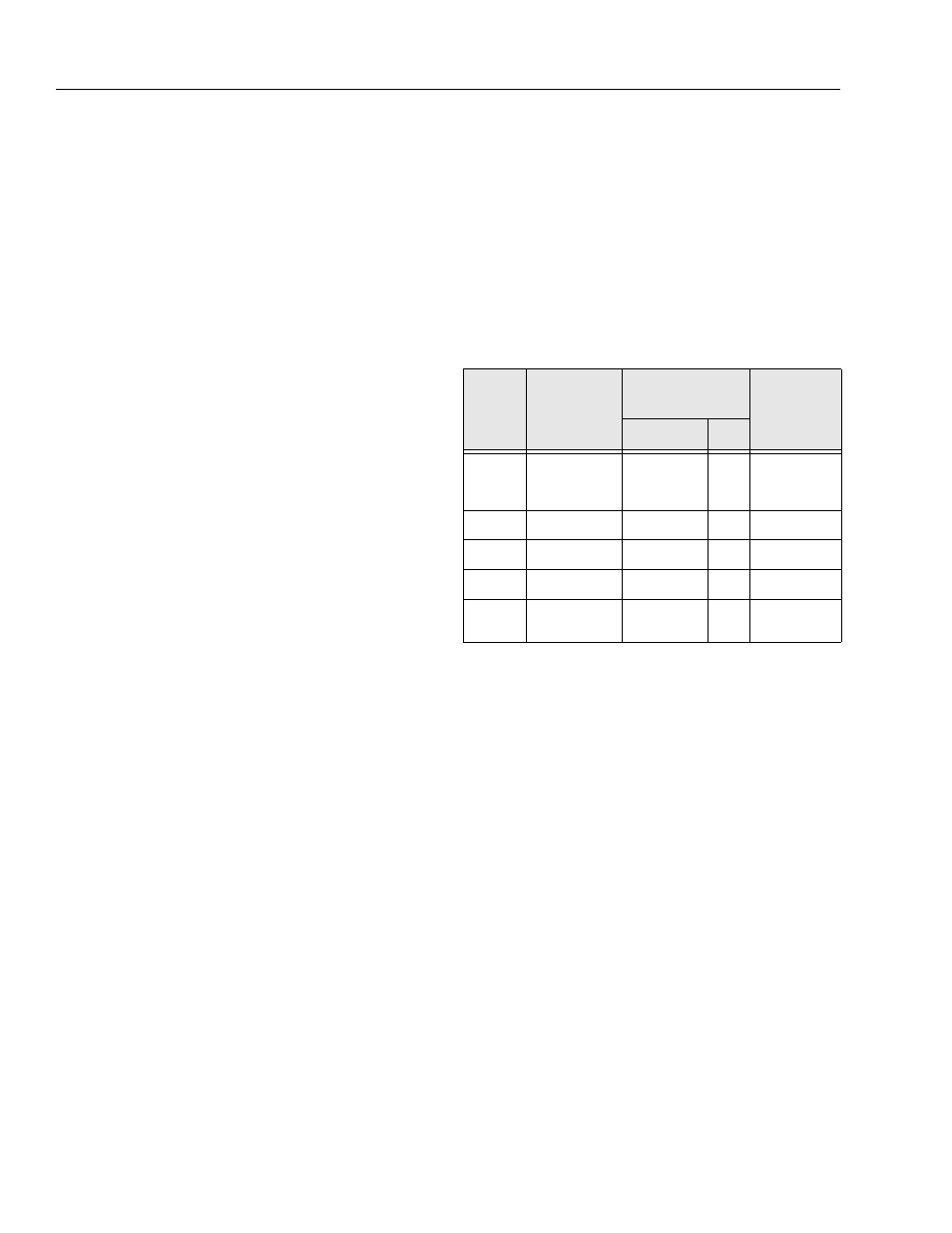
Ports and Pressure Gauges
Proper servicing of pumps and motors requires pressure
be measured and monitored at various points in the
hydraulic circuit. The Series 42 pump has several loca-
tions at which to take these measurements. The following
outlines show locations of various gauge ports. The fol-
lowing table shows recommended gauge size and fitting
size for each port.
NFPE Control
The 3-position FNR control, and electric and hydraulic
non-feedback proportional (NFPE and NFPH) controls are
non-feedback type controls. FNR and NFPE controls con-
sist of pump housing mounted modules. Hydraulic input
for NFPH is received through ports on top of pump [9/16–
18 SAE O-ring fitting].
The non-feedback controls are factory set. Control mod-
ules can be removed to clean ports and change O-rings.
Orifice plugs for the FNR and NFPE are located inside the
servo piston covers. Orifice plugs for the NFPH are
located in the NFPH ports. Orifice plugs may be cleaned
or replaced.
Table 5-4. Recommended Gauge Size
Gauge
Port
Name
Pressure
Measured
Recommended
Gauge Size
Fitting
PSI
Bar
M1 & M2
System
Pressure
Ports A & B
10000
600
9/16-18
ORF
M3
Charge
1000
60
3/4-16
ORF
M4 & M5
Servo
1000
60
9/16-18
ORF
L1 & L2
Case
500
35
1-1/16-12
ORF
S
Charge Pump
Inlet Vacuum
30 in. Hg Vac.
1
1-1/16-12
ORF