Valve plate and rear bearing -59, End cap -59 – JLG 450A_AJ Series II Service Manual User Manual
Page 109
SECTION 3 - CHASSIS & TURNTABLE
3121180
– JLG Lift –
3-59
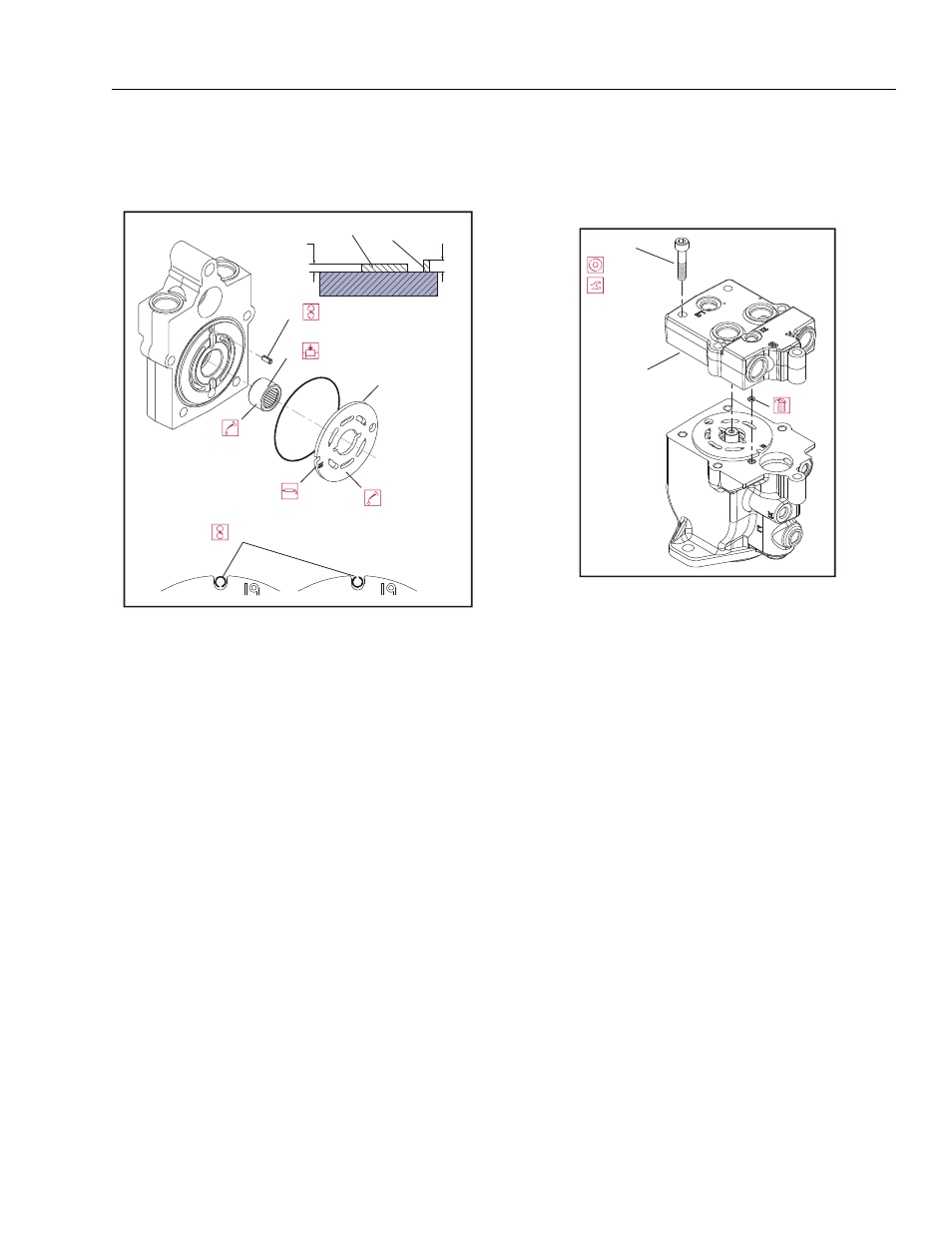
12. Press rear shaft bearing (22) into endcap. Install
bearing with letters facing out. Press until bearing
surface is 0.08 ±0.01 in (2 ±0.25 mm) above end-
cap surface.
13. Install timing pin (23) into bore in endcap. Install pin
with groove facing toward or away from shaft. Press
pin until end protrudes 0.12 ±0.01 in (3 ±0.25 mm)
above endcap surface.
14. Install valve plate (24) on endcap. Install valve plate
with yellow surface toward cylinder block. Align slot
in valve plate with timing pin. Apply a liberal coat of
assembly grease to endcap side of valve plate to
keep it in place during installation.
15. Install endcap (25) on housing with endcap screws
(26). Check endcap properly seats on housing with-
out interference. Improper assembly of internal com-
ponents may prevent endcap from seating properly.
Ensure O-rings seat properly when installing endcap.
16. Using an 8 mm internal hex wrench, tighten endcap
screws. Tighten screws in opposite corners slowly
and evenly to compress servo spring and properly
seat endcap. Torque endcap screws 35 to 45 ft-lb
(47-61 Nm).
17. Before installing shaft seal, ensure shaft turns
smoothly with less than 120 in-lb (13.5 Nm) of force.
If shaft does not turn smoothly within specified force,
disassemble and check unit.
23
23
22
24
3 mm
[0.12 in]
2 mm
[0.08 in]
23
22
22. Rear Shaft Bearing
23. Timing Pin
24. Valve Plate
Figure 3-42. Valve Plate and Rear Bearing
26
25
8 mm
(47-61 Nm)
35-45 ft.lbs.
25. End Cap
26. Screw
Figure 3-43. End Cap