Ecm inputs/outputs, Throttle position (tp) sensor – JLG 450A_AJ Series II Service Manual User Manual
Page 151
SECTION 3 - CHASSIS & TURNTABLE
3121180
– JLG Lift –
3-101
ECM Inputs/Outputs
Inputs—Operating Conditions
• Engine Coolant Temperature
• Crankshaft Position
• Exhaust Oxygen Content
• Manifold Absolute Pressure
• Battery Voltage
• Throttle Position
• Fuel Pump Voltage
• Intake Air Temperature
• Camshaft Position
Outputs - System Controlled
• Fuel Control
• Idle Air Control
• Electric Fuel Pump
• Diagnostics:
- Malfunction Indicator Lamp
- Data Link Connector (DLC)
ECM SERVICE PRECAUTIONS
The ECM is designed to withstand normal current draws
associated with engine operation. When servicing the
ECM, observe the following guidelines:
• Do not overload any circuit.
• Do not probe wires for testing. This can cause a volt-
age drop that affects ECM operation.
• When testing for opens and shorts, do not ground or
apply voltage to any of the ECM's circuits unless
instructed to do so.
• When measuring voltages, use only a digital voltmeter
with an input impedance of at least 10 megohms.
• Do not jump start with more than 12 volts. This can
damage electronic components.
• Do not use non-standard practices such as charging
the battery with an arc welder.
• Take precautions to avoid static damage to the ECM.
Refer to “Electrostatic Discharge Damage” for more
information.
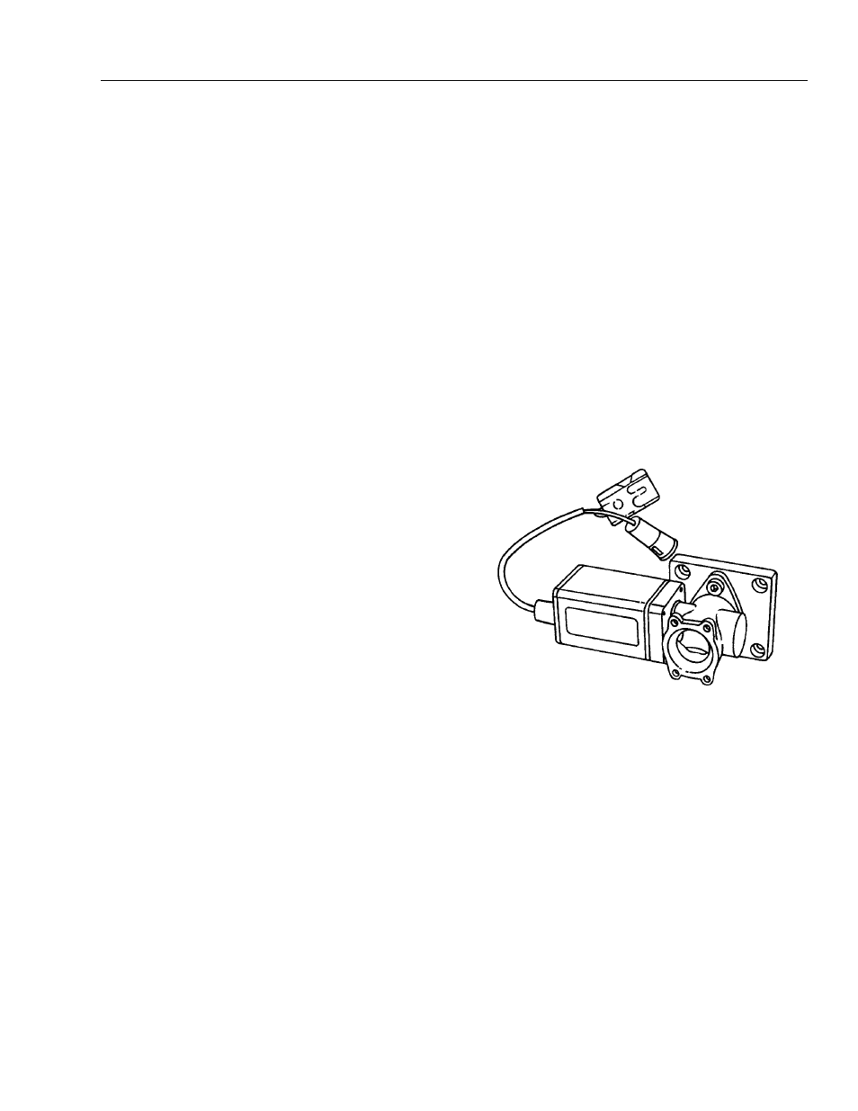
Throttle Position (TP) Sensor
The throttle position (TP) sensor is a potentiometer con-
nected to the throttle shaft on the throttle body, which is
built into the electronic governor. The ECM monitors sig-
nal line voltage and calculates throttle position. The TP
sensor signal changes as the throttle valve angle is
changed, At a closed throttle position, TP sensor output is
low. As the throttle valve opens, output increases so that
at wide open throttle (WOT), output voltage should be
above 4 volts.
The ECM calculates fuel delivery based on throttle valve
angle (operator demand). A broken or loose TP sensor
may cause intermittent bursts of fuel from an injector and
unstable idle because the ECM thinks the throttle is mov-
ing. A hard failure in the TP sensor 5-Volt reference or sig-
nal circuits for greater than 2 consecutive seconds will set
either a DTC 12 or DTC 22. A hard failure with the TP sen-
sor ground circuit for more than two consecutive seconds
may set DTC 22. If DTC 12 or DTC 22 are set, the throttle
is forced to a 6% (idle) position.