7 adjustment procedure for lockout valve, Lockout cylinder bleeding (early cylinders), Lockout cylinder bleeding (ram cylinders) – JLG 450A_AJ Series II Service Manual User Manual
Page 114: Adjustment procedure for lockout valve -64, Valve adjustment -64
SECTION 3 - CHASSIS & TURNTABLE
3-64
– JLG Lift –
3121180
3.7 ADJUSTMENT PROCEDURE FOR
LOCKOUT VALVE
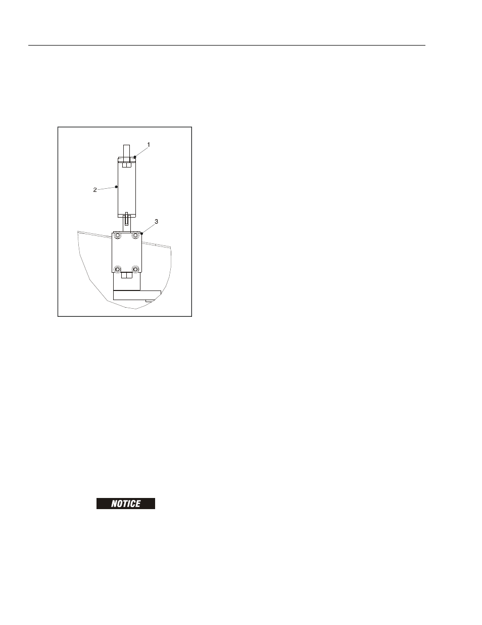
11. With turntable centered, adjust bracket with washers
to push plunger in 5/16" ± 1/16" (7.9 ± 1.6 mm).
1. The ideal adjustment is 3/8" (9.5 mm). Do not push
plunger in more than 3/8" (9.5 mm). The extra
adjustment is needed for turntable bearing play.
3.8 OSCILLATING AXLE BLEEDING
PROCEDURE AND LOCKOUT TEST
Lockout Cylinder Bleeding (Early Cylinders)
NOTE: The following procedure is for machines built in the
USA prior to S/N 0300107512 and machines built in
Belgium prior to S/N 1300003222.
FULLY LOWER PLATFORM AND CENTER BOOM OVER REAR AXLE
BEFORE STARTING BLEEDING PROCEDURE.
ENSURE MACHINE IS ON A LEVEL SURFACE AND REAR WHEELS
ARE BLOCKED, AND BRAKE WIRE IS DISCONNECTED.
1. Make sure machine is on a level surface.
2. Center boom over rear axle to make sure cam valve
in the rotary coupling is depressed.
3. Place chocks under tires to ensure machine does
not move. Disable machine brakes by disconnecting
brake solenoid(s) on brake valve.
4. Use suitable containers to catch excess hydraulic
fluid. Place containers under each lockout cylinder.
5. Open one bleeder screw at a time.
6. Start engine, position drive control lever forward or
reverse.
7. Close bleeder screws when all air is dissipated
(bled).
8. Reconnect brake solenoid(s) and remove wheel
chocks.
9. Perform oscillating axle lockout test.
10. If necessary, repeat steps 1 thru 7.
Lockout Cylinder Bleeding (Ram Cylinders)
NOTE: The following procedure is for machines built in the
USA S/N 0300107512 to present and machines built
in Belgium S/N 1300003222 to present.
1. Position turntable to normal stowed position so axle
is free to oscillate. Drive charge pressure will pass
through lockout valve built into swivel and down to
pilot section of holding valves on cylinders. This will
automatically purge air from pilot section of circuit.
2. Attach end of clear tubing to bleeder valve nipple
and place other end in container to catch oil. Using
a 3/8" wrench, slowly turn bleeder valve counter-
clockwise to bleed air from cylinder. Have operator
in platform just crack drive controller in reverse. This
will activate brake valve sending charge pressure to
lockout cylinder. Close valve when an unbroken,
steady stream of oil is seen.
3. Repeat procedure for other lockout cylinder.
1. Washer
2. Bracket
3. Lockout Valve
Figure 3-47. Valve Adjustment