Main assembly, Main assembly -18, Main assembly drawing1 -18 – JLG 450A_AJ Series II Service Manual User Manual
Page 68
SECTION 3 - CHASSIS & TURNTABLE
3-18
– JLG Lift –
3121180
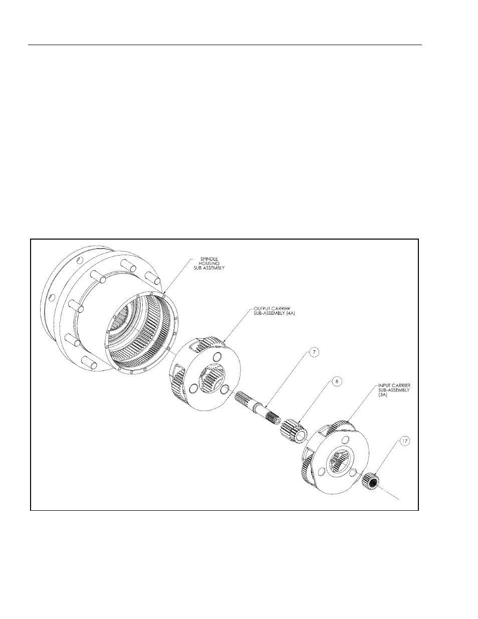
Main Assembly
NOTE: All components should receive a generous amount
of lubricant oil as they are being assembled.
1. Place Housing-Spindle Sub-Assembly on table with
Spindle (1A) side down.
2. Place Output Carrier Sub-Assembly into Housing
(1E) and onto Spindle (1A).
3. Insert larger diameter splined end of Input Shaft (7)
through bore of Output Carrier Sub Assembly (4A) until
shoulder of Input Shaft (7) contacts Thrust Washer (4J)
(See assembly drawing at back of manual).
4. With modified spline end facing up, place Output
Sun Gear (8) into mesh with planet gears from Out-
put Carrier Sub-Assembly (4A).
5. Place Input Carrier Sub-Assembly (3A) onto Output
Sun Gear (8) splines.
6. Grease O-Ring (19) and insert into groove in Cover
Sub-Assembly (6).
7. Install Cover Sub-Assembly (6) onto Housing (1E)
and install twelve Bolts (14) into Cover (6). Torque
bolts to 70-80 in-lbs.
8. Attach ID Tag (15) onto unit. If Cover has knobs as
part of cover, peen top of each knob to form a head
to hold on Tag. If no knobs, use drive screws.
9. Check disconnect, roll and leak check unit, leak
check brake, and check brake release pressure.
Figure 3-10. Main Assembly Drawing1
7. Input Shaft
8. Output Sun Gear
17. Input Sun Gear