JLG 450A_AJ Series II Service Manual User Manual
Page 134
SECTION 3 - CHASSIS & TURNTABLE
3-84
– JLG Lift –
3121180
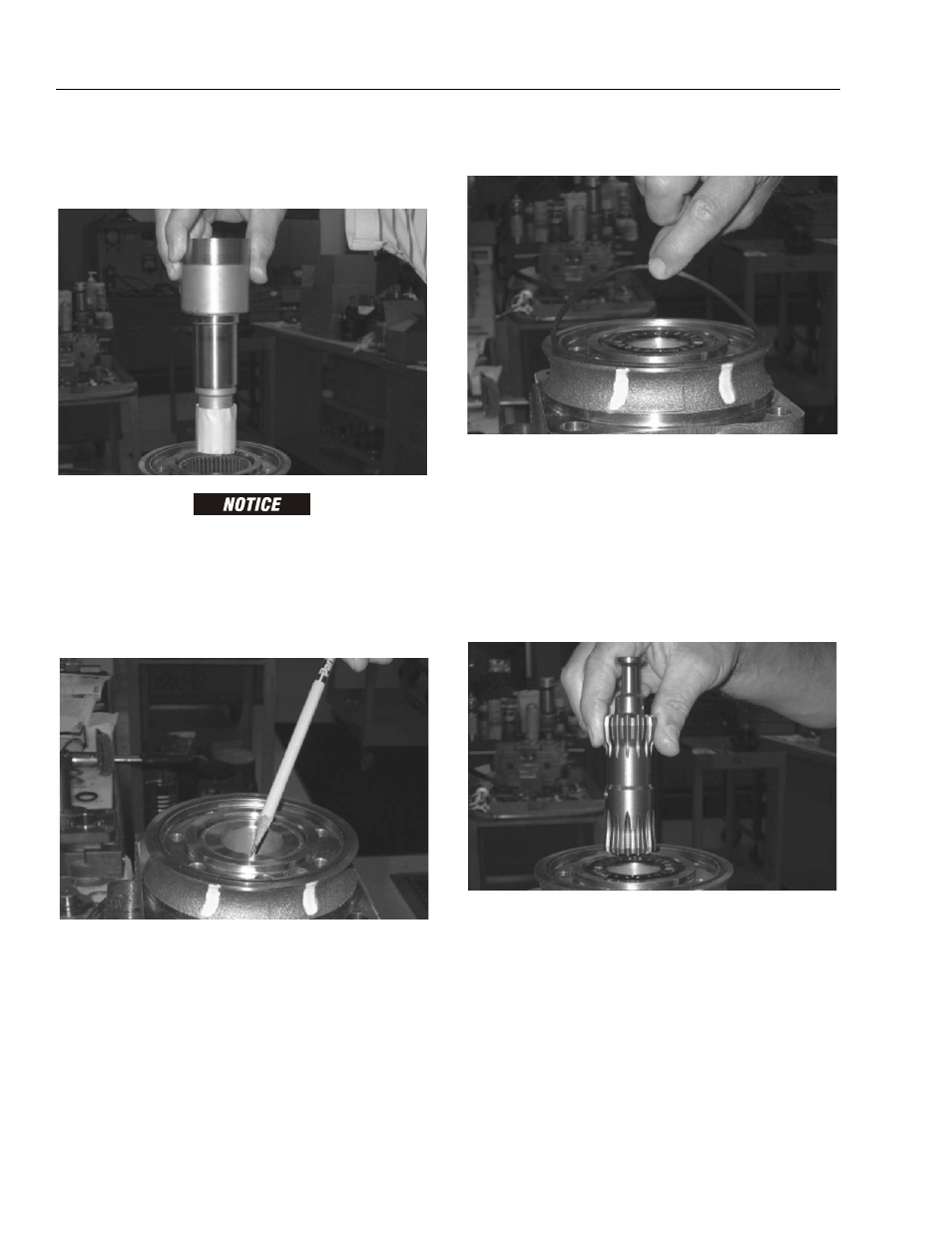
8. Apply a generous amount of clean, corrosion resis-
tant grease to lower (outer) housing bearing/bush-
ing (19). Install coupling shaft (12) into housing (18),
seating it against thrust bearing (15).
O U T E R B E A R I NG ( 1 9 ) I S N O T L U B R I C A T E D B Y S Y S T E M
HYDRAULIC FLUID. BE SURE IT IS THOROUGHLY PACKED WITH
RECOMMENDED GREASE.
NOTE: Coupling shaft (12) will be flush or just below hous-
ing wear surface when properly seated with coupling
shaft (12). Coupling shaft must rotate smoothly on
thrust bearing package.
9. Apply a small amount of clean grease to a new seal
ring (4) and insert it in housing (18) seal ring groove.
NOTE: One or two alignment studs screwed finger tight into
housing (18) bolt holes, approximately 180 degrees
apart, will facilitate assembly and alignment of com-
ponents required in the following procedures. Studs
can be made by cutting off heads of 3/8-24 UNF 2A
or 5/16-24 UNF 2A bolts as required that are over 0.5
inch (12.7 mm) longer than bolts (1) used in motor.
10. Install drive link (10), long splined end down, in cou-
pling shaft (12) and engage drive link splines in
mesh with coupling shaft splines.
NOTE: Use alignment marks on coupling shaft and drive link
before disassembly to assemble drive link splines in
their original position in mating coupling shaft
splines.