Mixer replacement, Coolant hose replacement, Mixer assembly -130 – JLG 450A_AJ Series II Service Manual User Manual
Page 180
SECTION 3 - CHASSIS & TURNTABLE
3-130
– JLG Lift –
3121180
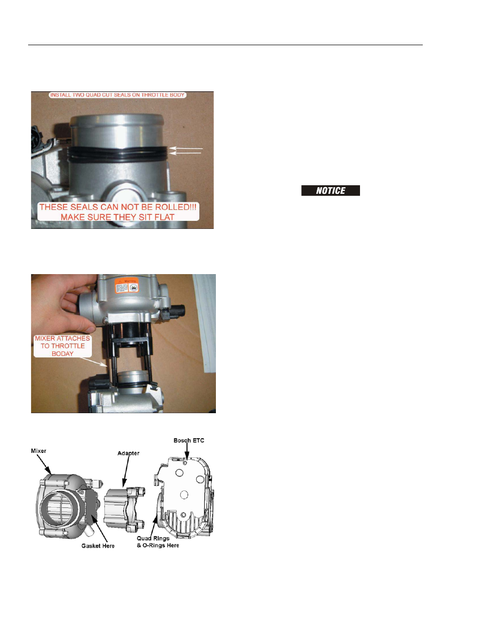
2. Install two quad seals one seal at a time so seal
does not roll. Seal must sit flat on throttle body.
3. Attach mixer and throttle body together. The two
parts do not bolt together; they will be secured when
you mount it on intake. Note orientation of air inlet
and throttle body cover.
4. Place gasket on intake manifold and attach mixer/
throttle assembly to manifold.
MIXER REPLACEMENT
See Figure 3-90.
REMOVAL
1. Remove Throttle control device. Refer to Electronic
Throttle Body Replacement.
2. Remove four (4) throttle control device to mixer
adapter bolts.
3. Remove discard mixer to adapter gasket.
INSTALLATION
COVER THROTTLE BODY ADAPTER OPENING TO PREVENT
DEBRIS FROM ENTERING ENGINE UNTIL REASSEMBLY.
1. Install Mixer to adapter gasket on mixer.
2. Install mixer on throttle control device to mixer
adapter and secure with 4 retaining screws. Tighten
80 in-lb(9 Nm)
3. Install Throttle body. Refer to Electronic Throttle
Control Device Replacement.
4. Start engine and leak check all fittings and connec-
tions.
Coolant Hose Replacement
REMOVAL
1. Drain coolant.
2. Using hose clamp pliers, disconnect both hose
clamps on each hose.
3. Remove hose from each fitting.
INSTALLATION
NOTE: Use hose material and lengths specified by JLG.
1. Install hose clamps to each hose. Set clamp back
on each hose to make installation easier.
2. Install hoses on fittings.
3. Secure by positioning each clamp.
Figure 3-90. Mixer Assembly